Content last revised on October 15, 2026
LG Display LM170E03-TLB3 Identification and Installation Checks
Disconnect the display harness with the equipment powered down, then compare the panel label and connector orientation with the assembly being replaced before applying power to the LM170E03-TLB3. Check the mounting tabs, cable clearance, and bezel contact points together: a connector that reaches its socket can still place unwanted strain on the display frame after the enclosure closes.
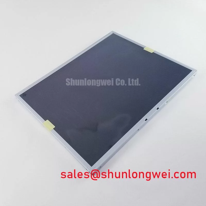
The LG Display LM170E03-TLB3 is a TFT-LCD active matrix color display module. Its product identification establishes the manufacturer and module category; the electrical supply, connector assignment, optical ratings, and environmental limits require the matching manufacturer datasheet. For replacement assessment, keep that document alongside the host schematic and mechanical drawing so that electrical compatibility and physical fit receive equal attention.
Surface Reflections and High Ambient Readability
Inspect the unpowered screen under oblique illumination to distinguish surface reflections from marks within the image area, then assess a grayscale pattern from the intended operator position. As a Design Consideration, anti-glare treatment redistributes reflected light, while anti-reflective treatment reduces reflection through an optical coating. These treatments have different effects on perceived sharpness and ambient contrast; neither treatment should be assigned to this model without its optical specification.
Viewing-angle assessment should include dark gray transitions and text backgrounds, rather than a bright image alone. As a Design Consideration, TN grayscale inversion and the angular behavior of IPS or MVA panels require different evaluation methods. A symmetric viewing cone quoted for another panel does not establish the LM170E03-TLB3 viewing performance. Check readability through the completed enclosure window because its reflections and spacing also affect the result.
Engineering Recommendation: establish the host signal interface before investigating pixel noise. LVDS differential signaling and parallel TTL signaling require different transmitter and receiver checks. For an LVDS connection, compare channel assignment, clock relationship, color mapping, and receiver timing requirements; where JEIDA or VESA mapping applies, match the transmitter configuration to the panel specification. Evaluate jitter and data timing at the receiver across the equipment’s intended temperature range.
For a high-voltage substation protection and SCADA dispatch console, compatibility evaluation should include viewing position, displayed alarm colors, enclosure reflections, and controller timing. When comparing the LM170E03-TLL1, compare its complete electrical and mechanical specification with the LM170E03-TLB3; the shared model prefix alone does not establish interchangeability.
Backlight Architecture and CCFL Ignition Troubleshooting
Trace the backlight harness to its power board before interpreting a dark screen as a panel failure. Engineering Recommendation: establish the installed backlight architecture, connector assignments, and inverter control functions from the matched assembly documentation.
For a documented CCFL assembly, a qualified technician can compare inverter enable behavior, lamp ignition, current regulation, and protection shutdown using suitable measurement equipment. As a Design Consideration, cold ignition demand depends on the lamp and inverter combination as well as temperature. Startup voltage must follow that combination’s specification; an assumed striking voltage can misdirect troubleshooting or exceed the assembly’s intended operating conditions.
Audible buzz should be assessed against brightness commands, mechanical mounting, and inverter operating behavior. Engineering Recommendation: observe whether the sound changes with dimming and whether illumination becomes unstable at the same time. These observations help separate control behavior from mechanical vibration without assigning a single cause from sound alone. Constant-current LED driver settings are relevant only to a separately documented LED assembly.
Ambient readability requires a separate optical check. As a Design Consideration, reflected illumination raises the apparent black level, so a dark-room contrast ratio cannot establish sunlight performance. Compare text and dark backgrounds under the actual installation lighting. Backlight lumen maintenance, lamp service life, and inverter reliability describe different properties and should remain separate when reviewing maintenance requirements.
Thermal and Mechanical Checks during Sustained Operation
Map enclosure and frame temperatures during sustained operation before changing brackets or adding heat spreaders. Engineering Recommendation: look for local heating near power electronics, restricted ventilation, and mounting points that constrain frame expansion. Choose any additional thermal path from measured temperatures and mechanical clearances, then check that it does not introduce pressure into the display assembly.
As a Design Consideration, uneven heating and mechanical constraint can contribute to optical nonuniformity in LCD assemblies. The general roles of scattering and light redistribution are described in Diffuser Optics; that background does not establish this panel’s internal film stack or light-guide material. Compare uniform test images before and after thermal stabilization with the enclosure assembled.
Engineering Recommendation: preserve differential-pair symmetry through the cable and connector transitions, then verify receiver timing with the complete harness installed. Where LVDS is confirmed, route assessment should consider discontinuities, return paths, and coupling from nearby switching circuits. The transmitter and receiver requirements determine the impedance and skew budget. Evaluate image stability during representative equipment operation rather than assigning the panel an independent system EMC rating.
For persistent grayscale errors, Engineering Recommendation: first check source color mapping and timing, then compare accessible timing-controller supply and reference measurements with the service documentation. Gamma correction affects grayscale transfer; arbitrary reference adjustments can obscure the original fault. The broader The Ultimate Guide to Industrial TFT LCD Technology provides background for separating interface, optical, and integration questions.
Storage Humidity and Environmental Handling
Engineering Recommendation: compare the manufacturer’s storage envelope with the complete packaging and handling procedure, including condensation control when moving a cold assembly into a warmer workspace. Inspect exposed connectors and screen edges before installation.
As a Design Consideration, liquid-crystal response generally slows as temperature falls, which can affect moving symbols and grayscale transitions. Evaluate the required screen content after thermal stabilization within the documented operating range. Background information on Amorphous Silicon TFT Technology explains a common display backplane technology; it does not establish this model’s response-time limits, sealing materials, or environmental qualification.
Engineering Recommendation: assess brightness control with the matched backlight power assembly while observing low-brightness stability, visible flicker, and audible behavior. Select the control waveform from the driver requirements and verify its usable adjustment range in the installed system. After environmental handling, compare uniform images for new edge discoloration, localized brightness changes, or mechanical distortion, recording the conditions before deciding whether further optical or electrical inspection is warranted.