


Content last revised on October 6, 2026
LM170E03-TLL4 Inspection and Documentation Checks
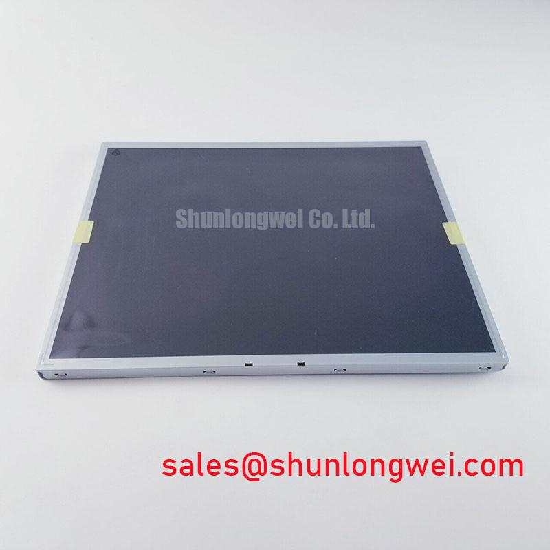
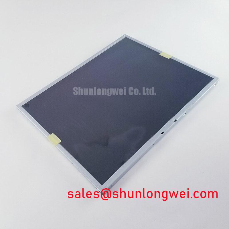
Inspect the connector and display surface of the LM170E03-TLL4 before applying power, then compare its label and mounting features with the panel removed from the equipment. LG Display identifies this model as a TFT-LCD display module (Official Factory Specification). For a repair assessment, the model match is a starting point, not proof that the host’s cable, supply, video timing and illumination circuitry are compatible.
During incoming inspection, I would record scratches, pressure marks and connector damage before running a full-screen image test. Solid white, black and primary-color patterns make different defects easier to locate; photographs taken at a fixed camera position help distinguish a persistent pixel defect from a reflection or a change in viewing angle. The supplied factory information does not state this model’s resolution, interface pinout, supply voltage, backlight type or operating-temperature limits. Those values should be checked against the original LG Display documentation and the host equipment drawing rather than inferred from the model name.
Checking Thermal Gradients and Optical Color Shift
Begin a thermal check only after confirming the correct electrical connections. Display a uniform white image, allow the module to reach a stable operating condition, and compare the center with the edges for brightness and color differences. A warm-looking strip near one side is an observation to investigate, not a diagnosis of a particular light-guide material or a prediction of yellowing. Repeat the observation with the equipment enclosure fitted: airflow, neighboring power electronics and the bezel can change the temperature pattern seen by the panel.
For an enclosure that transfers heat through narrow display edges, consider whether its support rails create a concentrated contact point or restrict airflow. This is a Design Consideration for the equipment assembly, not an LG Display mounting instruction for LM170E03-TLL4. Check the original mechanical drawing for permitted support areas and clearances before altering a bracket. The useful comparison is between a representative assembled unit and a known-good installation under the same image, ambient light and operating conditions.
Brightness drift deserves similar care. Record the test pattern, display control settings, viewing position and instrument geometry whenever measuring luminance. A changing reading can reflect the light source, its driver, optical contamination or test setup. The supplied factory information does not establish an LED light source, a rated half-brightness lifetime or a mean time between failures for this model. Any life assessment therefore needs the applicable backlight specification and defined operating conditions; a short bench run cannot establish it.
Checking Grayscale, Contrast and Viewing-Angle Effects
Check grayscale before judging contrast from a photograph. A stepped gray pattern viewed from the equipment operator’s normal position can expose crushed dark tones, washed-out highlights or an apparent inversion that changes with viewing angle. Rotate the viewing position in a controlled way and note whether the change affects the whole image or a localized area. Do not classify LM170E03-TLL4 as TN, IPS or MVA on the basis of this observation: its LCD mode and specified viewing angles are not included in the supplied factory information.
If the host uses a timing-control board, compare the video source, cable and board connections with the original schematic before adjusting image controls. Gray-scale errors can involve source timing, reference or gamma voltages, connection quality, or settings elsewhere in the display system. An oscilloscope comparison against a known-good signal path is more useful than assigning a single cause to a faint image. Measurements at a board test point must be interpreted against that board’s documentation; they are not automatically panel specifications.
Under strong ambient illumination, assess readability with the equipment’s actual cover lens and lighting arrangement in place. Reflections from the cover can dominate what an operator sees, even when the bare module looks acceptable on a bench. The supplied information does not identify a surface treatment or a dynamic-contrast function for this model, so neither should be assumed during procurement review. For an AGV or forklift telematics display, compatibility should be evaluated against the existing enclosure, operator sightline and original panel documentation rather than the application name alone.
Investigating Acoustic Noise and EMI During Brightness Changes
Listen for noise at the assembled display while changing brightness through the host’s supported controls, then separate sounds coming from the panel area from those coming from an external power or illumination driver. A tone that changes with brightness may justify inspecting the driver and its mounting, but it does not establish that the module uses a particular lamp technology or dimming method.
The original panel documentation must establish the illumination connection, driver requirements and power sequence before a technician connects a substitute driver. In particular, do not transfer CCFL ignition-voltage assumptions or LED constant-current settings from another display into this module’s test plan. Neither its backlight technology nor its rated lifetime is specified in the supplied factory information. If the host has a separate driver, compare its part number and wiring diagram with the removed assembly and observe its behavior using the equipment maker’s procedure.
Image disturbances that coincide with nearby servo activity call for a system-level signal-integrity check. Inspect connector seating, cable routing, shield continuity where the original design provides it, and the host power rails while the disturbance occurs. If the documented interface is LVDS, inspect its differential routing and termination against the transmitter and panel specifications; a general LVDS convention is not a verified impedance rating for this particular module. If the documented interface is different, use that interface’s timing and measurement method instead. EMC performance belongs to the assembled equipment and its tested configuration; the display module alone does not establish compliance.
💡 Bench Tip: Remove power, apply the bench’s ESD precautions, and align the display cable squarely before locking its connector.
Checking Cold-Start Gray Transitions and Image Stability
At a cold start, capture the first stable image and compare moving edges and gray transitions with the same unit after it has warmed under normal operation. Slower-looking transitions can be consistent with temperature-dependent liquid-crystal behavior, but a delayed or corrupted image can also come from host startup timing, an intermittent cable or an unstable supply. Log the ambient condition and elapsed time alongside the image evidence. The supplied factory information does not provide a gray-to-gray response-time rating or a permitted cold-start temperature for LM170E03-TLL4.
Inspect the perimeter and connector area after any temperature exposure for visible damage or changes in fit, without inferring an internal sealant formulation from the result. An equipment temperature target must not be treated as the panel’s operating limit. Designers should obtain the original temperature ratings and mechanical drawing, then verify the assembled display at the intended conditions. For broader test planning when evaluating thermal margin in an industrial enclosure, The Ultimate Guide to Industrial TFT LCD Technology provides context for separating panel limits from enclosure-level observations.
When the image fails only during startup, measure the panel supply at its documented connector pins and observe the host video signals during the same interval. Compare clock behavior, data setup and hold timing, and the order of power and video enable events with the original panel and transmitter documentation. The interface type and timing limits have not been supplied for this model, so a bench fixture should not be wired from an assumed LVDS or TTL pinout. Record the point at which the image becomes stable and repeat the check with the original cable position restored; movement-sensitive changes make the connector and harness worth examining before any timing adjustment.