Content last revised on September 14, 2026
LM170E03-TLL1 Inspection and Identity
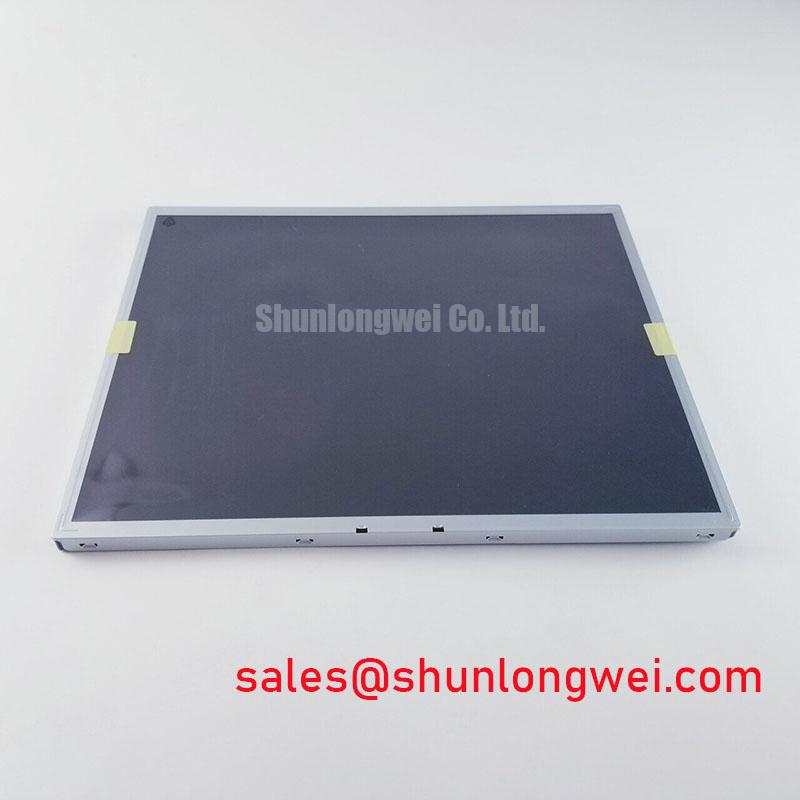
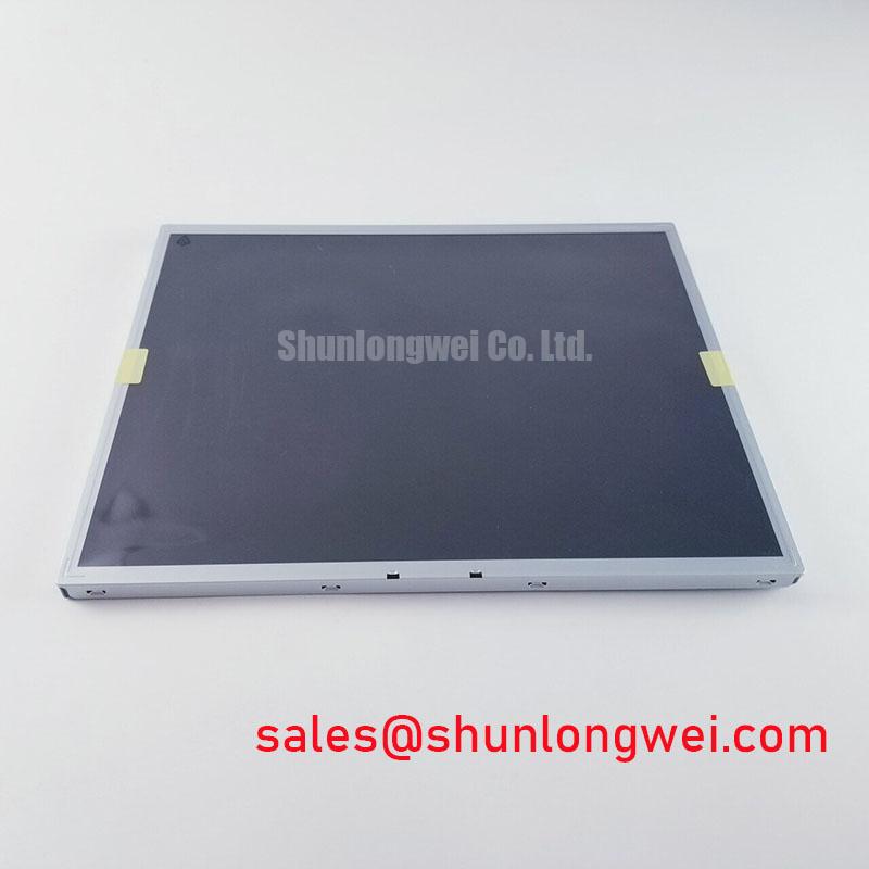
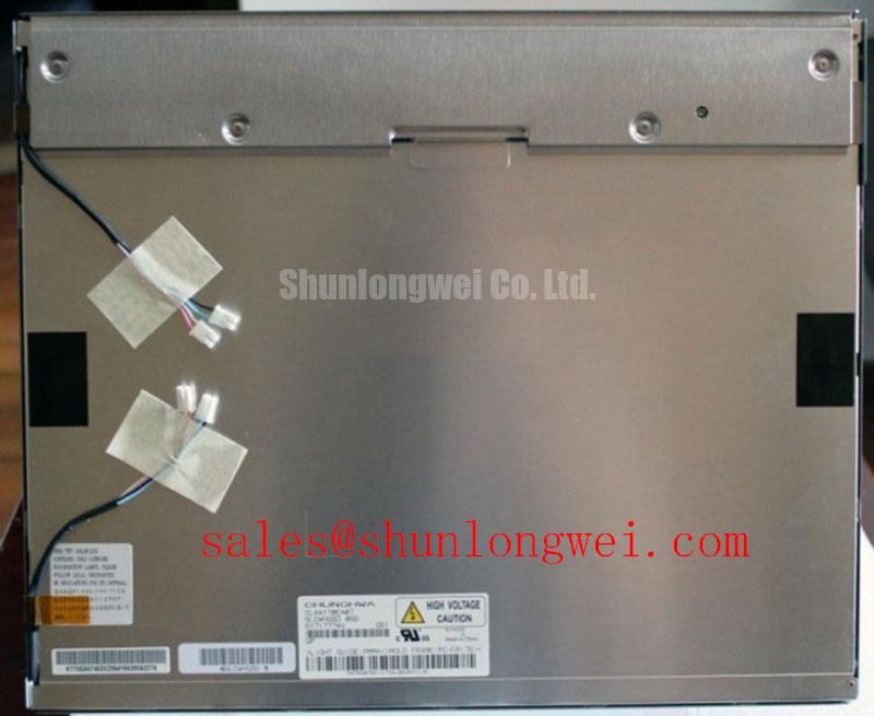
Start the bench inspection by checking the label, connector condition, glass edge, flex tails, and visible bezel damage on the LM170E03-TLL1 before applying power. Record the installed panel orientation and compare the replacement against the original unit. The verified product identity is LG Display LM170E03-TLL1, classified as an Industrial Grade LCD/HMI Panel and supplied as a TFT-LCD Display Module. The available factory specification context confirms the manufacturer, product category, package form, and official specification status, but it does not provide a complete electrical pinout, resolution, supply voltage, backlight rating, or mechanical drawing. Those values should be verified from the original panel documentation before system power is applied.
| Parameter | Verified information |
|---|---|
| Model | LM170E03-TLL1 |
| Manufacturer | LG Display |
| Product category | Industrial Grade LCD/HMI Panel |
| Package or assembly form | TFT-LCD Display Module |
| Specification status | Official Factory Spec Verified |
| Application evaluation | Industrial HMI, monitoring panels, surgical navigation displays, and ultrasound diagnostic terminals, subject to complete interface and mechanical verification |
For procurement and repair teams, the most important point is physical and electrical interchangeability rather than model number similarity. A panel with the same diagonal format may still differ in connector position, pin assignment, pixel clock requirements, image data mapping, backlight control, or mounting envelope. The system integrator should verify the required supply voltage from the original panel documentation. Do not infer a 3.3 V or 5 V rail, a particular LVDS lane count, or a specific backlight technology from the model designation alone.
Single Vertical Hairline Defect and Sub Pixel Column Driver Open Circuit Localization
When a single vertical hairline appears, begin with a controlled primary color bench test rather than immediately replacing the timing controller or display cable. Display full field red, green, blue, white, and black images through the known good source path. Observe whether the line remains fixed at the same column across every color, changes visibility with luminance, or disappears on a black field. A fixed line that persists through multiple test colors requires inspection of the panel signal path, connector seating, and bonded driver area. A defect that changes with brightness may also involve optical illumination, signal timing, or a local contact condition.
The second check uses oblique illumination. With the display operating at a safe, controlled brightness, direct a flashlight across the front surface at approximately 45 degrees and inspect the affected region from the opposite viewing angle. A dark shadow or uneven optical region that moves with the lighting angle can point toward a surface, diffuser, or backlight observation rather than a purely electronic column defect. This is a diagnostic observation, not a definitive failure signature. Avoid pressing the glass or bonded edge while testing because mechanical pressure can alter the symptom and create a misleading result.
The third step is comparison against a known good signal path. Confirm the source timing, cable seating, connector keying, and panel enable sequence before probing the receiver side. If the line is accompanied by intermittent noise, horizontal bands, or image tearing, inspect the differential clock and data pairs with an oscilloscope at suitable probing points. The result should be compared with the original operating panel under the same source conditions. Clock jitter margin and data hold behavior depend on the transmitter, cable, receiver, termination, temperature, and complete system timing budget; they are not established by the product name alone.
For LVDS installations, the design consideration is to preserve pair symmetry, controlled return paths, and consistent differential impedance through the cable and connector transition. A commonly used nominal differential impedance in display links is 100 Ω, but the system designer must confirm the interface requirement from the source board and the panel documentation. JEIDA and VESA data mapping are also not interchangeable assumptions. If colors appear shifted, grayscale steps are incorrect, or one color channel is overrepresented, verify the selected data format and bit mapping at the transmitter and T-CON interface.
The T-CON section should be assessed as part of the complete panel assembly. Gray-scale voltage generation, gamma correction, source-driver biasing, and timing control can influence banding or tonal discontinuity, but the correct reference levels are panel-specific. Do not substitute generic gamma values or adjust factory-set voltages without the applicable service documentation. When a defect is temperature dependent, compare cold-start and stabilized operation while monitoring the supply rails and image timing. A change across temperature may indicate a marginal interconnect, timing condition, or power integrity issue, so the measurement record should include the complete signal path rather than assigning a single cause to the panel.
Flush Mount Open Frame Bezel Integration and Perimeter Gasket Shock Isolation
Before mounting the LM170E03-TLL1 into an open-frame chassis, obtain the original mechanical drawing and confirm the visible area, mounting-hole pattern, connector clearance, glass edge position, and rear-component keep-out zones. The verified product information identifies the assembly as a TFT-LCD Display Module but does not provide the outer bezel envelope or mounting dimensions. The chassis cutout should therefore be derived from the approved panel drawing, not from a visually similar 17-inch display.
A flush installation should support the display through its intended mounting points while preventing the bezel, gasket, or front window from loading the active area. Perimeter sealing can help control dust, vibration, and light leakage, but compression should be distributed evenly around the frame. Localized force may produce temporary mura, dark corners, or nonuniformity that disappears after the panel is removed from the chassis. If the original equipment uses a gasket, record its contact location and condition before replacement. Do not improvise a rigid spacer across the active glass.
Fastener tightening is a system integration matter unless the original LG Display mechanical documentation specifies a value. A general design consideration for small display fasteners is to tighten gradually in a cross pattern and verify the result on the assembled chassis. The supplied engineering context cites a cross-pattern M3 torque range of 0.35 to 0.45 N·m as an integration guideline, not as a confirmed factory requirement for this model. Engineers should validate the actual torque against the chassis material, fastener type, gasket compression, and original service instructions.
💡 Pro Tip: Disconnect power before inserting or removing the display cable, and support the connector body rather than pulling the flexible cable.
After installation, inspect the panel at low, medium, and high image levels using white, gray, and black test fields. Ambient light can conceal low-level nonuniformity, so the evaluation should be repeated under the equipment’s actual viewing conditions. The available factory data does not verify a specific contrast ratio under 50,000 lux, nor does it confirm an anti-glare coating for this model. Those characteristics must be confirmed from the panel datasheet or inspected on the original unit before being included in a system specification.
For surgical navigation or ultrasound diagnostic display evaluation, the bezel opening and front-window stack should be checked with the display powered and unpowered. Confirm that the front window does not contact the panel surface during chassis flex, transport shock, or service access. Optical quality is affected by viewing angle, ambient reflection, surface treatment, image mode, and backlight condition. A mechanical fit that appears acceptable on a workbench may require additional validation after the enclosure, cable strain relief, and front cover are installed.
Engineers reviewing the mechanical and optical principles can refer to The Ultimate Guide to Industrial TFT-LCD Technology for broader context. That guide should complement, not replace, the model-specific drawing and service documentation for the LM170E03-TLL1.
Eye Diagram Voltage Margin and Differential Noise Floor Verification in High Vibration Bays
In a high-vibration control bay, first separate mechanical intermittency from electrical noise. Secure the display cable in its installed position, then observe the image while the enclosure is at rest and during the normal vibration condition. Inspect the connector latch, cable bend radius, strain relief, and contact alignment. If the symptom changes when the cable is moved, document the exact movement and compare it with the signal waveform rather than treating the visual symptom as proof of a failed panel.
LVDS cable routing should maintain a continuous reference path and avoid unnecessary proximity to switching nodes, motor-drive output conductors, and unfiltered power wiring. A 360-degree shield termination may be considered where the connector and chassis design support it, but the bonding method must be checked for ground-loop behavior and enclosure current paths. Ferrite components can reduce a selected common-mode noise mechanism, yet their suitability depends on frequency, impedance, current, placement, and the complete cable assembly. They should be evaluated through measurement rather than added as a universal remedy.
Eye-diagram testing is useful when the panel shows intermittent pixel jitter, horizontal noise bands, or unstable synchronization. Probe at an approved test location with a method that does not materially disturb the differential pair. Compare eye opening, common-mode behavior, edge quality, and timing against a known good assembly. The acceptable voltage and timing margin must come from the transmitter and receiver specifications together. The LM170E03-TLL1 information supplied here does not establish a universal eye-mask limit, receiver threshold, clock frequency, or data hold-time value.
Power integrity should be checked at the panel connector during startup, steady operation, and backlight transitions. A clean source-board rail does not guarantee a clean voltage at the display because cable resistance, connector contact, return-current coupling, and local decoupling affect the observed waveform. The original power-up sequence should be documented, including panel enable, video activity, and backlight control. If the required order or delay is unknown, the system integrator should verify it from the original panel documentation instead of applying a generic sequence.
For equipment containing variable-frequency motor drives or servo amplifiers, confirm chassis bonding and cable segregation while the display is in its final enclosure. A conducted-noise problem can resemble a timing or panel fault, while a timing mismatch can appear as a noise band. The diagnostic method should therefore combine visual test patterns, supply-rail measurements, differential waveform inspection, and cable substitution with a known good assembly. The panel itself should not be described as independently compliant with complete equipment EMC requirements; system-level compliance depends on the enclosure, harness, grounding, filtering, and operating configuration.
Backlight Drive Verification, PWM Dimming, and Flicker Control
Backlight compatibility must be confirmed before connecting the LM170E03-TLL1 to a replacement driver. The supplied factory parameter set identifies the display as a TFT-LCD module but does not verify whether the installed assembly uses a CCFL or WLED backlight, nor does it provide lamp ignition voltage, LED current, PWM range, half-life, or a backlight connector pinout. The system integrator should verify the required backlight supply and control method from the original panel documentation.
If the original assembly uses a CCFL circuit, inspect the inverter interface, insulation, enable signal, dimming signal, and lamp-current behavior according to the applicable service documentation. High-voltage ignition values must not be inferred from a general LCD repair reference. If a replacement design uses an LED constant-current driver, the driver must be matched to the actual LED string configuration, current requirement, enable polarity, and dimming interface. A driver that illuminates the panel is not automatically electrically compatible or optically equivalent.
PWM dimming should be evaluated with the complete display system, including the image source, backlight driver, camera-based inspection equipment, and the intended viewing environment. A stated 1000:1 PWM dimming capability is not a verified factory parameter for the LM170E03-TLL1 based on the information supplied here. Engineers should confirm the actual dimming specification before using it in a procurement or performance requirement. Flicker observations can vary with PWM frequency, duty cycle, camera exposure, and display refresh timing, so measurements should use an appropriate photometric or waveform method.
Backlight troubleshooting should begin with connector inspection and control-signal verification, followed by measurement of the driver output using equipment rated for the circuit. Acoustic noise, uneven brightness, or intermittent startup can involve the driver, cable, protection circuit, lamp or LED assembly, thermal conditions, or control timing. These symptoms should be recorded against a known good display or driver where possible. No specific operating life or MTBF value is confirmed by the available model data, so a claim such as 50,000 hours should not be assigned to this panel without an authoritative source.
For a replacement in a high-precision surgical navigation or ultrasound diagnostic display, validate grayscale reproduction after the backlight has stabilized, then check black level, white uniformity, color-channel balance, and brightness control across the intended operating range. Confirm that the T-CON receives the expected image format and that the gamma profile remains appropriate for the host system. If a resistive or capacitive touch overlay is installed over the LCD, its glove and moisture response belongs to the touch controller and cover-stack design; it should not be attributed to the LM170E03-TLL1 display module without separate documentation and testing.
Final integration approval should be based on the verified panel identity, confirmed interface mapping, documented power sequencing, mechanical drawing compliance, cable integrity, backlight compatibility, and image-quality testing in the completed enclosure.