

Content last revised on September 24, 2026
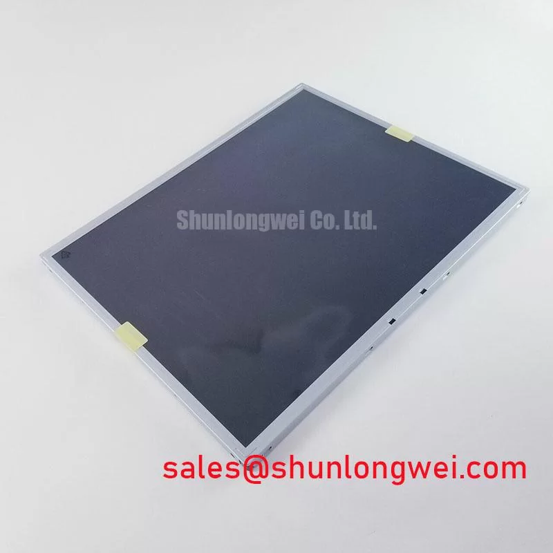
LM170E03-TLJ5 LG Display Industrial TFT LCD Module for HMI Panels
Begin incoming inspection by checking the LM170E03-TLJ5 label against the equipment documentation, then examine the TFT-LCD module for cracked glass, bent connector contacts, frame distortion, and visible contamination before applying power. This part is identified as an Industrial Grade LCD/HMI Panel manufactured by LG Display, with a TFT-LCD Display Module construction. The available factory information confirms the product category and manufacturer, but it does not provide enough verified electrical, optical, dimensional, or interface data to assign additional ratings to this specific unit.
For a CNC operator panel or robot teach pendant repair, compatibility should be established from the original panel documentation and the host controller pinout. The model number alone should not be used to infer the logic supply, backlight technology, connector assignment, resolution, viewing direction, or signal mapping. Those details can vary between display families and revisions. A replacement assessment should therefore compare the complete panel label, mechanical mounting points, connector position, cable orientation, controller output, and backlight driver requirements.
| Parameter | Verified information |
|---|---|
| Model | LM170E03-TLJ5 |
| Manufacturer | LG Display |
| Product category | Industrial Grade LCD/HMI Panel |
| Module form | TFT-LCD Display Module |
| Specification status | Official Factory Spec Verified for the listed identification data |
| Application evaluation | CNC operator panels and robot teach pendants, subject to system compatibility checks |
Backlight Architecture, Inverter Ignition, and Debugging
The first backlight question is not whether a replacement inverter can be connected, but whether the original equipment uses the same backlight architecture as the replacement panel. The supplied factory information does not confirm a CCFL tube arrangement, inverter topology, ignition voltage, operating current, or LED backlight configuration for the LM170E03-TLJ5. Engineers should verify these items from the original panel documentation before connecting a high-voltage inverter or a constant-current LED driver.
During bench evaluation, isolate the display from the machine controller and inspect the backlight harness, inverter board, enable line, dimming line, and return path. A panel that produces a faint image without illumination may involve the backlight circuit, inverter enable signal, cable seating, controller timing, or a protection response in the host system. This observation alone does not establish a single failed component. Compare the suspected panel with a known-good assembly using the same controller and measure the relevant signals with equipment rated for the circuit under test.
Do not transfer assumptions about a claimed 1500 to 1650 Vrms ignition range, a 1000 to 1 PWM dimming ratio, or a 50,000-hour half-brightness life to this model without a matching factory document. Those values are not included in the verified product information supplied for this page. A constant-current driver should only be considered when the panel documentation confirms LED backlight compatibility. Likewise, a CCFL inverter should only be used when the tube and electrical interface are documented as compatible.
Display data integrity should be checked separately from illumination. If the screen shows a stable image under an external light source but the backlight remains inactive, inspect the illumination path first. If the image contains intermittent bands, shifted data, or a loss of synchronization, trace the controller output, cable seating, and panel input together. The system integrator should verify the required supply voltage and signal standard from the original panel documentation rather than applying a generic TTL or LVDS assumption.
Bench Tip: Disconnect power before reseating the display cable, use ESD protection, and close the connector latch with the cable fully aligned and parallel to the socket.
Thermal Cycling and Display Seal Integrity Evaluation
Incoming inspection should begin at room temperature with a uniform full-screen test image, followed by visual examination under controlled illumination. Look for localized bright areas, dark patches, edge lift, pressure marks, liquid crystal irregularity, and changes that follow the perimeter or a mechanical mounting point. These observations can help separate optical non-uniformity from cable, controller, or enclosure pressure issues, but they do not identify a root cause without controlled comparison.
The available factory data does not verify an operating temperature range, storage temperature range, response-time rating, polarizer construction, adhesive specification, or perimeter sealant material for this specific model. Engineers evaluating the panel for equipment exposed to thermal cycling should obtain those limits from the original LG Display documentation. A general industrial design consideration is to prevent the enclosure, bezel, or mounting fasteners from applying uneven pressure to the glass during temperature change. The final mechanical arrangement should be validated with the actual enclosure and its thermal profile.
Low-temperature operation can alter liquid-crystal response behavior, while temperature gradients across the panel can influence perceived uniformity and startup performance. These are system-level considerations, not verified performance claims for the LM170E03-TLJ5. If a CNC control panel is tested in a chamber, record the image condition during ramping, stabilization, and return to room temperature. Check whether any symptom follows temperature, cable movement, controller state, or enclosure strain.
Gray-to-gray response testing should use a defined measurement method and a calibrated photometric instrument. A subjective impression of slow transitions is not sufficient to assign a GTG value. The same caution applies to seal integrity: visible edge changes should be documented photographically and correlated with mounting pressure and thermal exposure, rather than attributed to a particular adhesive or gasket without source data.
For engineers reviewing long-term operating suitability, the The Ultimate Guide to Industrial TFT LCD Technology provides broader background on TFT-LCD operating principles, selection factors, and common evaluation issues. The model-specific limits still need to come from the applicable factory specification.
Polarizer and Optical Surface Inspection under Direct Industrial Lighting
Optical inspection is most useful when the panel is tested with repeatable content: full white, full black, primary colors, neutral gray steps, and a fine checkerboard. Observe the center, corners, edges, and any area near the bezel. Record visible color shift, luminance non-uniformity, pixel defects, image retention, and changes when the viewing angle moves horizontally and vertically. The test should be performed without touching the active surface, since finger pressure can create temporary optical artifacts.
The verified information for LM170E03-TLJ5 does not specify the panel mode, viewing angle, contrast ratio, anti-glare treatment, retardation film, surface hardness, or optical performance under direct sunlight. It would therefore be inaccurate to describe this model as IPS, MVA, or TN, or to assign a symmetrical 85°/85°/85°/85° viewing cone. Those characteristics must be confirmed against the correct manufacturer document.
For an industrial HMI, direct lighting can reduce perceived contrast even when the panel itself is operating normally. A controlled optical check should note the ambient condition, viewing direction, test image, and instrument position. Do not treat a single contrast value, including a proposed value above 500:1 at high illumination, as a verified specification for this model unless the source document defines the measurement method and test conditions.
Surface inspection should identify scratches, coating marks, pressure-related clouding, and contamination separately. Clean the surface only with a method approved for the panel finish. Avoid abrasive materials and excessive localized force. When a panel is installed behind a protective window, evaluate reflections and the air gap as part of the enclosure assembly, because the finished HMI optical result depends on the complete stack rather than the display module alone.
Grayscale and gamma evaluation also requires care. A T-CON or host controller may apply its own timing and gamma behavior, so a visible gray-step issue should be compared with a known-good panel on the same electronics. If the fault follows the controller, inspect the signal chain and configuration. If it remains with the display, document the pattern and operating condition for supplier or manufacturer review.
Display Cable Routing and Signal Integrity Evaluation
Before connecting the LM170E03-TLJ5 to a replacement controller, confirm the connector keying, pin numbering, cable direction, logic standard, pixel mapping, clock arrangement, and enable sequence from the original documentation. The verified product information supplied here does not confirm LVDS, TTL, JEIDA, VESA, 3.3 V, 5.0 V, a 100-ohm differential requirement, or a specific power-on timing window. These values must not be treated as model specifications without supporting documentation.
Where the host system uses differential display signaling, the design team may evaluate controlled-impedance routing as an engineering consideration. Keep paired conductors together, avoid unnecessary stubs, maintain a consistent reference plane, and separate sensitive display paths from noisy motor, inverter, and servo wiring. The correct characteristic impedance is determined by the transmitter, receiver, cable, connector, and system layout. It should be verified with the applicable interface documentation and, where necessary, signal-integrity measurement.
Clock jitter and data hold behavior should be examined at the panel interface with an oscilloscope and suitable probing method. A split image, unstable vertical region, missing color component, or intermittent synchronization may indicate a mapping, timing, cable, connector, or power-sequencing issue. These symptoms should be compared with a known-good signal path rather than assigned to one cause immediately. The system integrator should verify the panel’s required rise-time and enable sequence from the original panel documentation.
Power testing should monitor the supply at the panel connector during startup and image changes. Check for voltage droop, ground offset, connector resistance, and noise coupled from nearby switching equipment. The host controller should be powered down before cable insertion or removal, and any discharge interval required by the equipment service procedure should be observed.
For CNC operator panels and robot teach pendants, final validation should combine a static image test, moving graphics, grayscale transitions, backlight control, repeated startup, cable flex observation, and electromagnetic interference testing at the complete assembly level. The display module itself should not be described as independently certified for EMC compliance. System-level compliance depends on the controller, enclosure, cable routing, grounding, shielding, and installation conditions.