Content last revised on October 21, 2026
LTM170E8-L21 Panel Identification and Replacement Checks
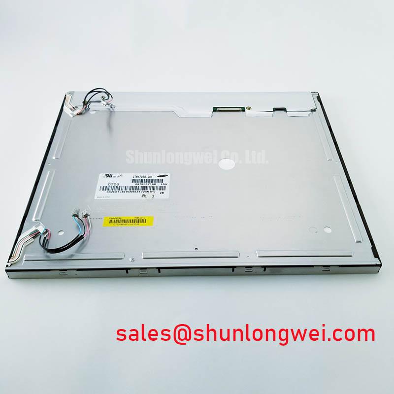
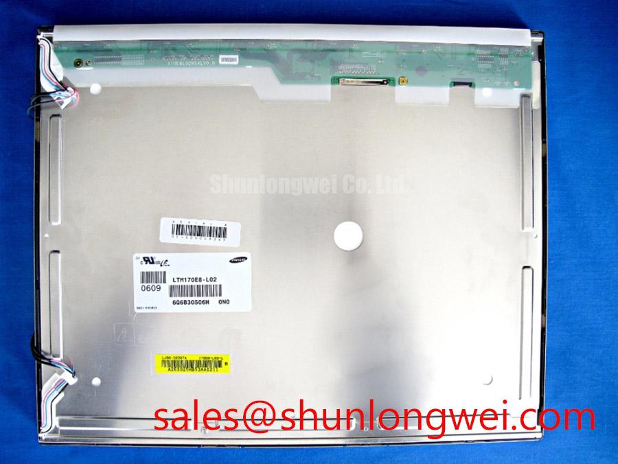
- Check the existing panel label and connector orientation before removal.
- Inspect the bezel opening, mounting holes, gasket contact area, and rear clearance.
- Record the original display interface, backlight arrangement, and controller power sequence.
- Confirm insulation, cable routing, and cooling airflow before energizing the replacement panel.
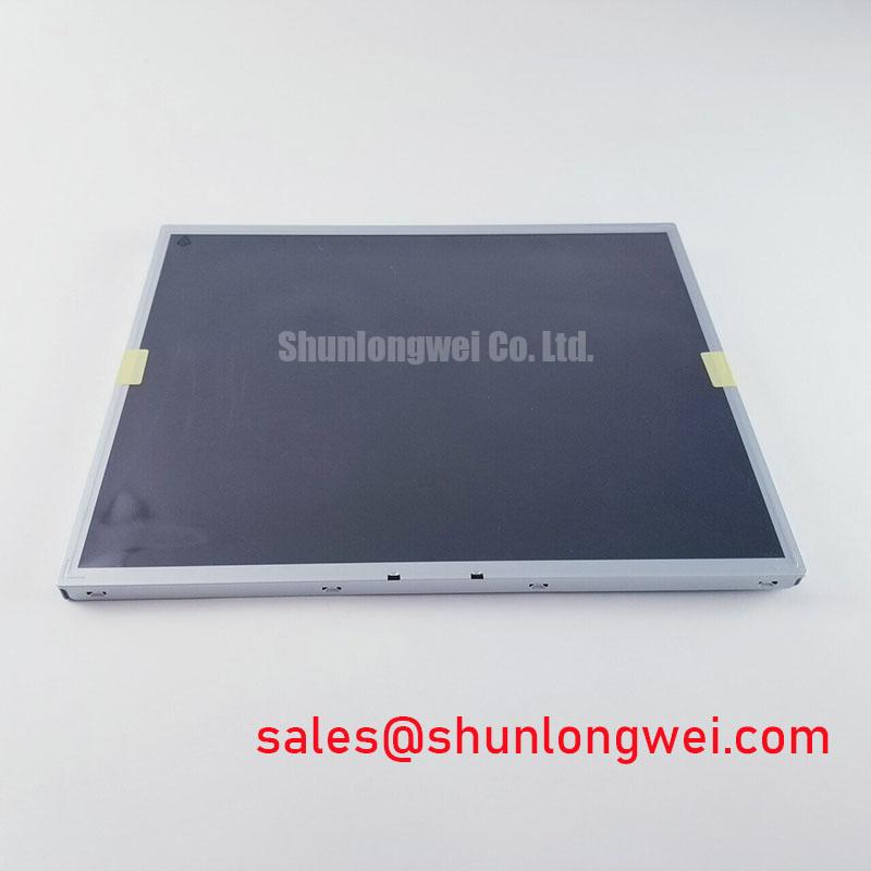
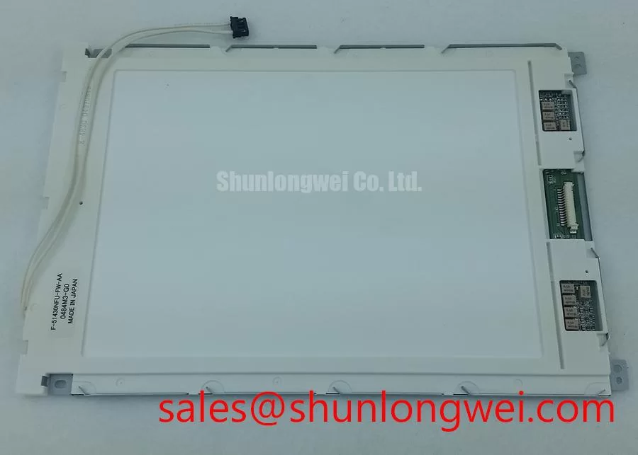
LTM170E8-L21 is a Samsung TFT LCD active matrix color display module. When evaluating it for industrial HMI and panel replacement work, verify the exact model suffix and original equipment requirements. The information available here does not establish confirmed resolution, luminance, interface voltage, connector pinout, viewing angle, or backlight ratings, so those values must be checked against the model-specific documentation before replacement.
| Product category | TFT LCD panel |
| Manufacturer | Samsung |
| Display construction | TFT-LCD active matrix color display module |
| Specification verification | Confirm model-specific electrical, optical, and mechanical requirements before installation |
| Reference product page | LTM170E8-L21 product information |
Industrial Bezel Mechanical Envelope Tolerances & Mounting Screw Torque
Start mechanical evaluation with the bezel opening rather than the panel electronics. The display should sit evenly against its gasket or front frame, with no corner lifted by cable pressure, uneven fastener loading, or interference from the cabinet cutout. A general form-factor description does not replace a dimensional drawing; compare the original panel’s visible area, mounting hole pattern, connector position, and rear depth before installation.
For a maintenance build, use a cross-pattern tightening sequence so the frame settles progressively instead of loading one edge first. The available product information does not define an official screw torque for this model. Any M3 torque value used by the equipment builder should therefore be treated as a Design Consideration taken from the chassis and fastener specification, not as a factory rating of the display. Excessive local compression can alter optical uniformity and create dark-field mura or localized light leakage.
High-speed display wiring also needs mechanical separation from motor and contactor conductors. Where the host interface uses differential signaling, designers should preserve the transmitter’s controlled impedance and pair symmetry through the cable, connector, and board transition. A commonly used engineering target is 100 Ω differential impedance with skew controlled to the system budget, but these are interface design values rather than confirmed LTM170E8-L21 specifications. Confirm signal integrity at the receiver under the actual cabinet noise conditions.
When a service alternative is being evaluated, compare the mounting envelope, active area, connector assignment, and timing requirements rather than relying on diagonal size alone. The M185XW01 VB page provides information on a different panel for material planning; it does not establish compatibility with LTM170E8-L21.
Temperature Qualification & Sub-Zero Liquid Crystal Viscosity
Cold-start testing should focus on image response, uniformity, and condensation control at the same time. Liquid-crystal viscosity rises as temperature falls, which can produce visible gray-to-gray response lag during the first minutes after energization. At elevated temperature, bezel expansion, seal stress, and internal heat distribution become more relevant to long-term image stability.
A range such as −30°C to +85°C must not be treated as an operating rating for this model without supporting manufacturer documentation. Use such an evaluation range only when it is supported by the panel documentation and the host equipment environmental specification. A thermal chamber or controlled cabinet test should observe startup behavior, black-field uniformity, grayscale transitions, and the perimeter seal after repeated temperature changes.
Direct sunlight can expose weaknesses in contrast, surface reflection, and viewing-angle compensation. A stated contrast target such as greater than 500:1 at 50,000 lux must come from a verified optical datasheet or a measured system test; it should not be assigned to this model from the category description alone. The general LCD operating principles described in Liquid-Crystal Display Polarizers and Optical Glass help explain why polarizer condition, cover-window reflection, and viewing angle affect field readability.
For factory HMI cabinets, designers should manage warm-up airflow and prevent humid air from reaching a cold display surface. The gasket should remain continuous around the bezel, while the cabinet ventilation path should prevent concentrated hot spots behind the panel. ⚠️ Maintenance Note: Inspect the bezel gasket and cabinet cooling path during scheduled service so dust loading or seal compression does not create uneven pressure or condensation exposure.
Backlight Driver Identification, Dimming & Flicker Suppression
Backlight identification must be completed before connecting a replacement. The information available here does not establish the LTM170E8-L21 backlight drive requirements or provide verified backlight voltage, current, PWM level, or dimming ratio. Do not connect a generic driver based on connector appearance; match the original power architecture, enable logic, polarity, and fault behavior.
Some industrial display systems use high-voltage CCFL ignition, while others use constant-current LED drivers. A cold-ignition figure in the 1500 to 1650 Vrms class, a 1000:1 PWM dimming ratio, or a backlight half-life and MTBF figure must be supported by the relevant panel or inverter documentation before being associated with this model. These values are not confirmed product specifications here.
For LED-based systems, assess current balance across the backlight strings, switching noise at the display connector, and visible flicker at low brightness. For PWM control, verify that the host controller’s logic level and timing are accepted by the driver. The same inspection should include audible noise from the driver, because magnetics or switching components can produce acoustic artifacts even when the screen image appears normal.
Interface timing deserves a separate check from backlight control. Confirm the transmitter clock, data hold interval, reset behavior, and power-on order against the original controller documentation. If a TTL or LVDS interface is present, the system engineer should verify clock jitter and receiver margin across the intended temperature range rather than infer compatibility from the panel model number.
Suppressing Pixel Jitter & Horizontal White Lines Induced by Adjacent 400V Motor Drives
When the HMI is installed near a variable-frequency motor drive, route display data away from the switching output conductors and terminate the cable shield according to the cabinet’s grounding architecture. Pixel jitter and horizontal bands can arise from several interacting conditions, including common-mode coupling, poor reference continuity, connector seating, and timing margin loss. The visible symptom alone does not establish one cause.
A shielded FFC or LVDS cable should be supported without sharp bends at the connector entrance. Maintain the original contact orientation and fully engage the locking mechanism before power is applied. Designers should minimize parallel exposure to high-current motor wiring and keep the display return path deliberate, with final verification performed using a known-good signal path and oscilloscope measurements at the receiver.
Common-mode ferrite components may be evaluated where cabinet testing shows conducted interference, but their impedance curve, placement, and grounding effect must be selected for the actual interface. They are not identified as supplied accessories for LTM170E8-L21. A nominal 100 Ω differential target and a 50 ps skew budget may be used as system-level design references only when they match the controller and cable specification.
Power sequencing is equally important during troubleshooting. Observe the order of panel supply, logic enable, video transmission, and backlight activation to distinguish a true data-path problem from an initialization or display-enable issue. For broader selection guidance on optical interfaces, environmental factors, and industrial TFT integration, consult The Ultimate Guide to Industrial TFT LCD Technology. Sunlight-readable systems may also use local-dimming architectures, whose general behavior is outlined in Mini-LED backlight local dimming architecture; that technology should not be assumed to be part of this display.