



Content last revised on October 4, 2026
Display Data Mapping and Signal Alignment
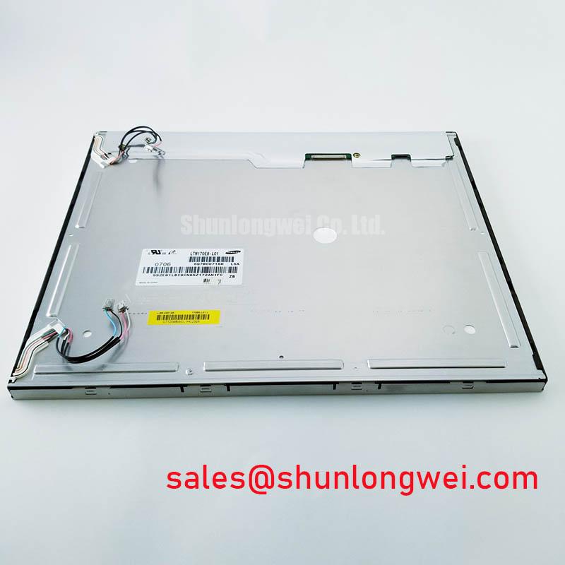
Check the LTM170E8-L02 label against the removed display, then photograph its connectors and mounting points before disconnecting the assembly. The supplied product identification describes a TFT-LCD display module in the industrial LCD/HMI panel category. It does not establish the panel’s supply voltage, connector pinout, dimensions, backlight type or optical ratings. Those details must be checked against the original panel documentation and the equipment assembly before a replacement decision is made.
A matching connector shape does not establish electrical compatibility. For the LTM170E8-L02, the system integrator should verify the required supply voltage, connector orientation, signal assignment and power sequence from the original panel documentation. Record the controller board part number as well: equipment revisions can retain a similar display opening while changing the harness or display interface.
If the documented interface uses LVDS, compare the transmitter configuration with the panel’s specified data mapping and channel assignment. VESA and JEIDA mappings, where applicable, place color bits differently; an incorrect mapping can produce recognizable but inaccurate colors. An incorrect channel assignment can produce displaced or divided image content. Neither symptom proves a panel fault on its own. Confirm the mapping in the controller documentation and inspect the waveform at the panel connector before assigning the cause.
Signal integrity is a Design Consideration for a replacement harness or controller layout. Keep differential routing consistent with the documented interface and check connector seating, cable damage and shielding where the equipment design provides it. Clock quality and data timing should be assessed against the applicable transmitter and panel specifications across the equipment’s intended temperature range, rather than inferred from an image that happens to appear during a room-temperature bench test.
Managing Heat and Optical Color Shift
Before fitting the LTM170E8-L02 into an enclosure, inspect the space around the display edges, ventilation path and any adjacent heat-producing electronics. Uneven heating can contribute to visible color variation over time, but a yellow-looking image does not identify one material or failure mechanism. Compare a uniform test image with a known-good assembly, if available, and check whether the appearance changes after the enclosure reaches its normal operating condition.
Heat-spreading rails or other chassis changes are Design Considerations, not specified features or required accessories of this module. Any proposed change should preserve the panel’s mounting clearances and be evaluated with temperature measurements at accessible chassis locations. It should not press on the display edge to obtain thermal contact. The supplied identification does not confirm an LED backlight, a light-guide material or a backlight life rating, so none should be used as a replacement criterion without the original specification.
Dust and condensation deserve separate checks during equipment maintenance. Inspect the enclosure gasket for gaps, compression damage and contamination, then examine the ventilation path without assuming the display itself provides an environmental seal. Where a machine moves between cold and warm conditions, allow the equipment to reach a suitable service condition before interpreting a temporary optical change as a permanent panel defect. The broader enclosure questions are covered in Industrial Display & HMI Solutions.
Mounting Stress and Visible Mura
Compare the original display’s outer envelope, mounting locations, connector clearance and bezel contact surfaces with the proposed installation. The supplied product information does not verify an M3 fastener size or a model-specific torque limit. Use the equipment maker’s mechanical instructions for fastener selection and tightening; do not transfer a torque value from another display assembly.
Support the chassis evenly as fasteners are brought into contact, and watch the powered image for changes while the bezel is fitted. A dark-field image can make pressure-related bright or dark patches easier to see, although similar-looking marks can have other causes. If a mark appears only after assembly, loosen and refit the surrounding hardware according to the equipment procedure, then compare the image again before attributing the mark to the LCD module.
Maintenance note: Check the ventilation path and enclosure gasket during scheduled service, and disconnect power before reseating the display cable.
Separating Image-Path Faults From Backlight Faults
Start with the symptom as observed, not a presumed failed part. Note whether the panel is completely dark, faintly shows image content, displays lines, or produces incorrect colors. Compare the controller’s output and the display connector with a known-good signal path where one is available. Check supply and enable signals only against values in the original equipment and panel documentation.
For a dark screen, an angled flashlight inspection can help reveal whether faint image content is present while illumination is absent. It is a screening observation, not a definitive backlight diagnosis: controller settings, cabling, supply faults and panel circuitry still need to be checked. For lines or partial images, reseat the cable using the equipment procedure and inspect its contacts and routing before concluding that a display driver has failed.
A bench test can then use uniform primary-color images supplied by a compatible controller to compare color rendering, missing regions and brightness uniformity. Record the result before and after the panel is installed in its bezel; a change after installation is useful evidence when examining mechanical contact. For a CNC operator panel or robot teach pendant, assess the LTM170E8-L02 only after the equipment’s interface, physical fit and environmental requirements have been confirmed.