

Content last revised on September 10, 2026
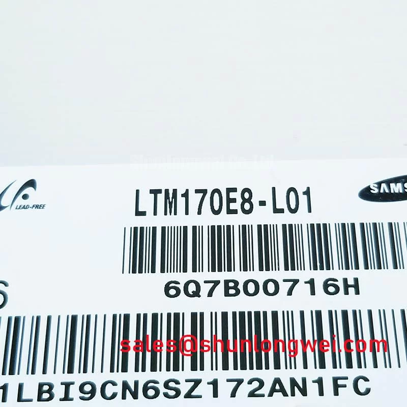
LTM170E8-L01 Panel Overview and Installation Checks
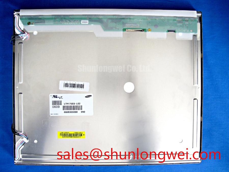
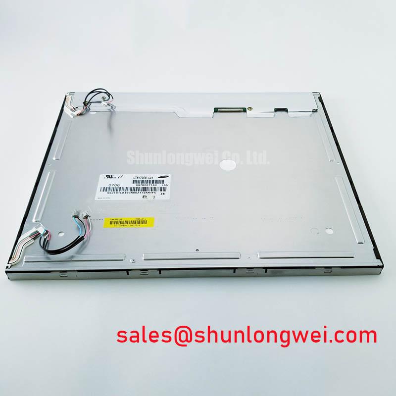
Before connecting the LTM170E8-L01, inspect the 30-pin LVDS connector, confirm that the mating harness is fully seated, and verify the host panel supply against the required 5.0 V typical input before power is applied.
The LTM170E8-L01 is a 17.0-inch TFT LCD panel specified with 1280 × 1024 SXGA resolution, a 5:4 aspect ratio, RGB vertical-stripe pixels, and a PVA, normally black, transmissive display mode. Its official optical specifications include 280 cd/m² typical luminance, 1000:1 typical contrast ratio, 16.7 million colors, and a typical 89/89/89/89° viewing angle at CR≥10. The panel uses a 2-channel, 8-bit LVDS interface through a 30-pin connector.
| Parameter | Official Specification |
|---|---|
| Model | LTM170E8-L01 |
| Manufacturer Identification | Samsung |
| Screen Size | 17.0 inches |
| Resolution | 1280(RGB) × 1024, SXGA |
| Aspect Ratio | 5:4 |
| Display Technology | PVA, Normally Black, Transmissive |
| Brightness | 280 cd/m² typical |
| Contrast Ratio | 1000:1 typical |
| Viewing Direction | 89/89/89/89° typical, CR≥10 |
| Color Depth | 16.7M colors, 8-bit |
| Surface | Antiglare, 3H hard coating |
| Signal Interface | LVDS, 2-channel, 8-bit, 30-pin connector |
| Panel Supply | 5.0 V typical |
High-Nits Edge-Lit LED Rail Thermal Dissipation and Light Guide Preservation Assessment
The official information for the LTM170E8-L01 identifies its panel optics, interface, and electrical supply but does not define its backlight construction, LED arrangement, light-guide material, rail dimensions, or thermal operating limits. Service engineers should therefore avoid assuming an edge-lit LED architecture or assigning a thermal-life expectation to this exact display without the original equipment documentation.
When a display assembly is installed behind a sealed industrial bezel, the practical inspection point is the enclosure rather than an assumed internal rail design. Check whether the panel perimeter is compressed evenly by the gasket, whether ventilation channels are blocked by dust accumulation, and whether nearby power supplies or processors are radiating heat directly toward the rear of the LCD assembly. Uneven panel clamping can contribute to localized optical stress that becomes visible as pressure marks or uneven luminance during a dark-image inspection.
The specified 280 cd/m² typical luminance should be evaluated as an official optical rating, not as a guarantee of readability under direct outdoor sunlight. For bridge-console, navigation, or industrial monitoring equipment, the system integrator should evaluate ambient light, protective-window reflections, enclosure geometry, and the original dimming implementation under actual operating conditions.
Cold ambient conditions can slow the visible transition behavior of liquid-crystal displays. This is a Design Consideration rather than a published LTM170E8-L01 temperature rating. If the host equipment is expected to start in low-temperature conditions, technicians should compare image response, color uniformity, and startup behavior with a known-good panel and verify any enclosure heater-control strategy using the original equipment documentation.
⚠️ Maintenance Note: Isolate power before reconnecting the LVDS cable, and periodically inspect the display gasket and cooling path for contamination or compression damage.
Incoming Benchtop Inspection for LVDS Signal Integrity and Line-Defect Screening
A controlled bench check starts with a compatible host controller configured for the panel’s 1280 × 1024 SXGA format and its specified 2-channel, 8-bit LVDS interface. Confirm that the panel receives the required 5.0 V typical supply from the host system before interpreting an inactive image as a panel defect. The required signal timing, power sequence, and connector pin assignment should be verified from the original panel and equipment documentation.
A practical image inspection uses full-screen red, green, blue, white, gray, and black test patterns. Solid primary-color fields help reveal vertical or horizontal line irregularities, while white and gray fields make uneven brightness, pixel anomalies, and localized discoloration easier to identify. A black pattern is useful for checking whether unwanted light appears around the perimeter or within the active area.
A flashlight inspection at an oblique angle can help separate surface contamination, antiglare-coating marks, and external bezel pressure from image defects visible only during powered operation. It should not be used as a definitive diagnosis of internal bonding or driver damage. If a line defect changes with cable movement, panel flexing, or controller substitution, the technician should inspect the full signal path and compare behavior against a known-good harness and source board.
The antiglare 3H hard-coated surface is intended to reduce reflections and provide a harder outer surface, but it remains important to clean it with a panel-safe process approved for the equipment. Aggressive solvents, abrasive materials, or excessive pressure can alter the visible surface condition and complicate later optical assessment.
The panel’s 16.7M-color, 8-bit specification describes supported color depth. Color depth and color gamut are related but distinct display concepts; integrators evaluating image-source quality can consult Color Depth and Color Gamut Standards and Color Gamut Coverage for broader terminology.
High-Humidity Storage Margins and Enclosure Delamination Prevention Practices
No official high-humidity storage limit, thermal-cycle range, perimeter seal construction, or delamination performance figure is stated in the supplied LTM170E8-L01 specification. Such conditions should therefore be treated as a system-level Design Consideration. The panel should remain within the environmental boundaries specified by its original documentation and by the equipment manufacturer’s enclosure requirements.
For equipment stored in humid workshops, dockside facilities, or unconditioned cabinets, examine the enclosure before fitting the panel. Look for failed gasket contact, trapped moisture, corrosion around mounting hardware, damaged protective windows, and cable-entry paths that can allow humid air to reach the display cavity. A clean, dry mounting surface helps the bezel gasket apply even pressure without introducing local stress points across the LCD.
Condensation management should be evaluated at the equipment level. A display can appear functional during a brief bench test yet be exposed to moisture risk when a sealed enclosure is moved between cold storage and a warm operating environment. Designers should verify the original housing venting, heater, conformal-protection, and drainage provisions rather than modifying the panel assembly based on generic assumptions.
LVDS transmission also deserves attention in electrically noisy control cabinets. Differential-pair routing, reference continuity, connector engagement, shielding strategy, and cable placement should be reviewed when intermittent sparkles, image noise, or synchronization loss are observed. The system engineer should validate signal quality at the panel connector against the known-good signal path and host timing requirements. The 30-pin LVDS connector must be supported so cable strain is not transferred directly to the panel connection.
For a broader technical reference on panel selection, display operating principles, and integration misconceptions, see The Ultimate Guide to Industrial TFT LCD Technology.
Optical Luminance Degradation Checks and Backlight Modernization Evaluation
The LTM170E8-L01 has an official 280 cd/m² typical luminance rating and 1000:1 typical contrast ratio. These values describe the specified panel characteristics under the manufacturer’s stated test conditions; they do not establish a field operating lifetime, brightness-retention curve, backlight type, or replacement interval. A service decision should be based on comparison with the original equipment display performance and the applicable panel documentation.
When an older control terminal appears dim, first separate optical loss from upstream causes. Verify panel supply stability, controller output, LVDS cable seating, image settings, enclosure-window contamination, and any external brightness-control circuitry before attributing the symptom to the LCD. A uniformity check using white and gray test images can show whether the issue is broadly distributed or limited to one region of the active area.
Any CCFL-to-LED modernization discussion is a system retrofit evaluation, not an inherent feature of the LTM170E8-L01. The supplied official specifications do not identify the installed backlight technology, ignition requirements, dimming method, PWM range, acoustic behavior, or lifetime figure. Engineers considering a retrofit should verify the original mechanical stack-up, optical coupling, power architecture, thermal path, control interface, and regulatory obligations for the complete equipment.
The panel’s normally black PVA transmissive mode, wide specified viewing angle, and antiglare surface can be relevant when evaluating replacement compatibility in industrial HMI terminals, process displays, or navigation-console equipment. For applications such as a marine radar or navigation bridge console, final suitability remains dependent on the host enclosure’s sealing, light-management design, system environmental requirements, and verification against the original equipment configuration.