
Content last revised on September 24, 2026
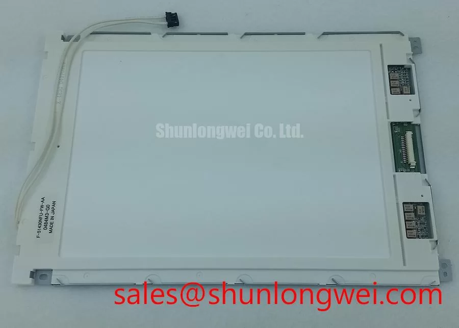
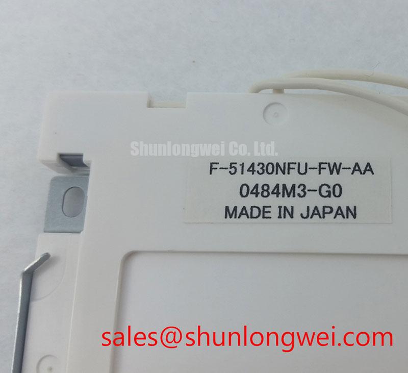
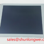
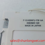
AUO F-51430NFU-FW-AA Industrial LCD Display for Field Replacement
Begin the service inspection by checking the display label, connector condition, bezel, and visible panel damage against the equipment documentation before applying power. The F-51430NFU-FW-AA is identified here as an AUO Industrial Grade LCD/HMI Panel in a TFT-LCD Display Module package. The available factory information does not establish every electrical, optical, dimensional, or interface value required for a direct replacement, so the original panel documentation and the machine wiring must remain the controlling references.
This product is relevant to engineers assessing an industrial automation CNC operator panel or a robot teach pendant. In those systems, a compatible replacement depends on more than the visible screen format. The connector position, interface protocol, logic supply requirement, backlight architecture, touch overlay, mounting envelope, and controller timing must all be checked before installation. A display with a similar appearance can still be unsuitable if its electrical interface or mechanical loading differs from the original assembly.
| Model | F-51430NFU-FW-AA |
| Manufacturer | AUO |
| Product category | Industrial Grade LCD/HMI Panel |
| Package | TFT-LCD Display Module |
| Specification status | Limited product information available |
| Reference product page | AUO F-51430NFU-FW-AA product information |
Logic Supply Voltage Sequencing for Industrial HMI Integration
Before connecting the panel to a CNC control or robot pendant, identify the exact logic supply voltage and signal standard from the original panel documentation. The supplied product data does not confirm whether this model is intended for a particular 3.3 V or 5.0 V system, so the system integrator should not infer the required voltage from connector appearance alone. Confirm the supply rail, enable signals, backlight control, ground arrangement, and connector pin assignment using the equipment schematic or the original display assembly.
Power sequencing deserves attention during a bench replacement test. Apply the control board and display supply in the order specified by the equipment manufacturer, then observe the rise of the logic rail, reset behavior, display enable state, and backlight command. An incorrect sequence can produce a blank image, intermittent startup, abnormal current demand, or controller protection behavior. These symptoms do not identify one single failure cause; compare the replacement panel with a known good signal path and record the measured voltage at the panel connector.
For differential display links, route each pair as a controlled transmission path with a continuous reference plane and short return current paths. The commonly used 100 ohm differential target is a Design Consideration for an applicable high speed interface, not an official electrical specification confirmed for this exact AUO model. The integrator should verify whether the panel uses LVDS, TTL, or another interface before applying any routing rule. The same caution applies to JEIDA and VESA data mapping. Incorrect mapping can appear as incorrect colors, split images, reversed pixel groups, or unstable grayscale reproduction.
Clock quality should be checked at the receiver or at an accessible test point with suitable measurement equipment. Review clock jitter, data setup and hold behavior, pair polarity, termination, and ground reference across the intended operating temperature range. If a display shows intermittent artifacts only when a servo amplifier or spindle drive operates, inspect cable shielding, cabinet bonding, connector retention, and common mode coupling before changing the panel configuration. Power switching equipment can influence display reliability at the cabinet level; the Infineon PrimePACK™ reference provides context for the power semiconductor environment, but it is not a specification source for this AUO LCD module.
When the machine uses a T CON or display controller board, verify grayscale voltage generation, gamma configuration, and timing parameters against the original assembly. A mismatch in gamma correction may leave the image visible while producing incorrect mid tones, crushed shadows, or excessive highlight clipping. These observations should be documented as comparison results rather than treated as proof of a particular internal fault.
Backlight Architecture and Ignition Troubleshooting in Legacy Equipment
Determine the backlight technology from the original panel documentation and the installed inverter or driver before energizing a replacement. The supplied factory data does not confirm a CCFL arrangement, an LED arrangement, the number of channels, ignition voltage, current regulation method, PWM frequency, or dimming range for the F-51430NFU-FW-AA. It is therefore unsafe to assume that a legacy inverter can be connected to a replacement display simply because the connector appears similar.
For equipment using a high voltage fluorescent backlight system, inspect the inverter harness, insulation, connector locking features, and chassis clearance with power removed. A cold start problem can involve the inverter, lamp circuit, cable insulation, control signal, or the display assembly. Use the original service procedure and an appropriately rated test instrument. Do not probe a high voltage backlight circuit with general purpose equipment or with the panel exposed to conductive debris.
For an LED backlight system, verify the driver output configuration, current regulation, enable polarity, dimming method, and thermal arrangement. A constant current driver intended for a different LED string can cause an overcurrent condition or fail to start. PWM brightness control should be checked for visible flicker, acoustic interaction with cabinet components, and stable operation at the machine controller’s commanded levels. Any numerical PWM frequency or duty cycle requirement must come from the panel or driver documentation rather than from a generic replacement guide.
Uneven brightness requires a visual and electrical comparison. Inspect the panel in a controlled image condition, then examine the driver current, cable seating, thermal contact, and surrounding airflow. Dark areas, edge brightness variation, or flicker may originate in the backlight, diffuser assembly, power driver, signal timing, or mechanical pressure. Avoid assigning the symptom to a single component without measurements.
Long operating life claims also require source control. No field lifetime, half life, or MTBF value is asserted here because such data has not been supplied as an official specification for this product page. The maintenance team should use the original AUO documentation and the machine builder’s environmental limits when estimating service intervals. A display installed in a sealed operator panel may require a different thermal review from one installed in an open teach pendant, even when the visible image is identical.
Temperature, Condensation, and Image Response During Factory Operation
Before installing the module in an enclosure, compare the actual cabinet temperature profile with the environmental limits recorded for the original display. The supplied product information does not confirm a wide temperature operating range for this exact model, so values attributed to similar industrial LCD families should not be transferred to it. Measure temperature near the display surface, behind the panel, and close to the controller during representative machine cycles.
Sub zero startup can change liquid crystal response behavior and may produce slower transitions, temporary image lag, or a change in grayscale appearance. These effects should be assessed by allowing the assembly to reach a stable temperature while monitoring image uniformity and controller timing. A cold display that appears slow is not automatically defective, and a normal image after warming does not prove that the enclosure has adequate environmental protection.
Condensation is a separate risk from low temperature. If a cold panel is moved into a warm and humid service area, moisture can form on connectors, the bezel, or internal surfaces. Let the assembly equalize in a controlled environment before applying power, following the site’s electrical safety procedure. Check enclosure seals, cable entry points, ventilation paths, and any gasket contact surface during scheduled maintenance.
High frequency factory equipment can disturb a display through radiated or conducted coupling. Keep display signal routing separated from motor output cables where the machine layout permits, preserve shield continuity across cabinet boundaries, and verify the return path at the controller and panel ends. A 100 ohm differential routing target and pair skew control may be relevant design considerations for an applicable LVDS link, but the actual interface requirements must be confirmed for this AUO model and validated with an oscilloscope or suitable compliance method.
Wide viewing angle behavior should also be evaluated from the operator’s normal position rather than from a single perpendicular inspection angle. IPS or MVA terminology must be confirmed from the original documentation before it is used in a procurement specification. Observe color shift, grayscale stability, and contrast at the viewing angles required by the CNC operator panel or robot teach pendant. If the system has a touch overlay, verify that the overlay does not obstruct the active image area or create an unacceptable calibration offset.
⚠️ Maintenance Note: Inspect the cabinet airflow openings, display gasket contact, connector strain relief, and signs of condensation during planned maintenance, especially after washdown or seasonal temperature changes.
For a broader explanation of panel interface behavior, timing, selection factors, and common assumptions, engineers can consult The Ultimate Guide to Industrial TFT LCD Technology. That guide provides general engineering context; it does not replace the AUO documentation for the F-51430NFU-FW-AA.
Mechanical Fit, Bezel Pressure, and Optical Uniformity Checks
Confirm the outer bezel envelope, mounting hole pattern, connector clearance, cable bend path, and front sealing arrangement before placing the display into a CNC operator panel or robot teach pendant. The available official parameter set does not provide dimensional tolerances or fastener specifications for this model, so the original mechanical drawing must control the installation. Do not force a connector or use the bezel to pull a panel into alignment.
Mechanical stress can affect optical uniformity even when the electronics are functioning correctly. During installation, support the module evenly, align the chassis without twisting, and tighten fasteners in a cross pattern only when the equipment drawing specifies that method. Torque values supplied for other display assemblies must not be presented as AUO factory requirements for this product. If the drawing provides no torque value, the responsible mechanical engineer should determine a controlled installation method from the fastener, bracket material, gasket, and enclosure design.
After fastening, display a neutral gray image and inspect the corners, edges, and center under consistent lighting. Localized brightness variation may be associated with bezel pressure, bracket distortion, cable interference, or an optical assembly condition. Release the mechanical load in a controlled test if permitted by the service procedure, then compare the result. This approach separates installation influence from an electronic image problem without assigning a single cause prematurely.
Dust sealing should be checked around the complete perimeter rather than only at the visible front edge. A compressed or displaced gasket can permit contamination and may also create uneven loading. Confirm that the enclosure frame is flat, the gasket surface is clean, and the panel is supported at the intended contact points. The sealing method must remain compatible with the machine’s cleaning chemicals, vibration environment, and thermal expansion behavior.
Finally, verify the completed assembly under actual machine conditions. Check image stability while the CNC axis drives, spindle, robot servo, or pendant cable is active. Review touch response if a touch layer is fitted, including operation with the approved gloves and with the surface condition expected at the workstation. Any replacement decision should be based on the confirmed interface, mechanical drawing, environmental requirement, and measured system behavior rather than on model appearance alone.