Content last revised on October 21, 2026
Optical Luminance Degradation Curve and CCFL to LED Modernization Retrofit Pathways
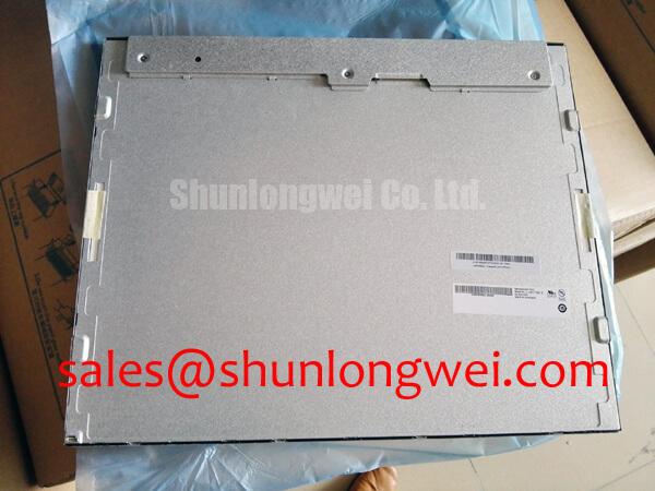
When evaluating a replacement M195FGE-P03, I first run a full white screen and a mid-gray screen at controlled display settings, then compare center and edge luminance with the known-good unit. This separates backlight aging from T-CON timing, gamma correction, and signal-chain faults before any retrofit decision is made.
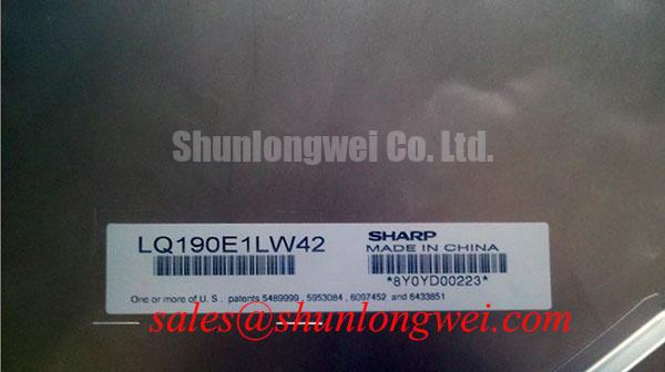
The available product definition identifies this unit as a TFT-LCD active matrix color display module from Innolux / AUO. It does not establish a universal CCFL or LED backlight configuration for every system carrying this model reference, so the original panel documentation and the installed backlight harness must control the replacement assessment. A CCFL assembly requires evaluation of its inverter, high-voltage wiring, ignition behavior, acoustic noise, and lamp current regulation. An LED conversion requires a compatible constant-current driver, correct dimming control, thermal clearance, and optical matching with the existing light guide and diffuser arrangement.
Do not treat a retrofit driver’s advertised PWM ratio, half-life estimate, or brightness figure as a specification of the M195FGE-P03. Those values belong to the selected backlight system and must be tested as an assembly. Under direct sunlight or high-bay industrial lighting, contrast stability depends on the panel surface, cover glass, ambient reflections, black-level control, and installation angle. Anti-glare performance should therefore be checked with the final bezel and protective window fitted, rather than judged from the bare module.
For a system-level display chain, the related LQ10D421 may be reviewed as a separate display solution in the surrounding architecture. It should not be assumed to be a plug-compatible backlight driver or electrical substitute for this panel without matching connector, timing, power, and mechanical documentation.
Polarizer Durability and Optical Retardation Film Inspection under Direct Industrial Lighting
Under strong workplace illumination, inspect the screen at full white, 50 percent gray, black, and saturated color fields while changing the viewing angle slowly. Look for localized haze, rainbow coloration, pressure marks, nonuniform darkening, and viewing-angle color shifts. These observations help distinguish surface damage from optical nonuniformity originating deeper in the panel stack.
The model classification confirms an active matrix color display module, but it does not provide a verified TN, IPS, or MVA designation in the supplied product parameters. For that reason, a symmetrical viewing cone or a specific grayscale inversion behavior should not be assigned to this model without the applicable panel datasheet. The same caution applies to claims about retardation film construction, anti-glare etching, or optical compensation layers.
For incoming inspection, use the same luminance level and image patterns for every sample. A clean polarizer surface should be checked for scratches, edge lifting, contamination, and compression marks around the mounting area. Cleaning should follow the equipment manufacturer’s approved procedure; aggressive solvents or excessive pressure can alter the surface finish and create defects that resemble panel nonuniformity.
Backlight aging is best tracked by recording luminance against operating time under the actual driver and thermal conditions. A nominal service-life figure from an LED supplier is not an official endurance rating for the complete M195FGE-P03 assembly. Thermal distribution behind the panel, ventilation around the bezel, and local heat from nearby electronics can change the observed degradation curve.
💡 Bench Tip: Wear ESD protection and insert the display cable squarely before locking the connector, because a partially engaged flexible cable can create intermittent color, line, or backlight symptoms.
Wide Temperature Operational Margin and Sub-Zero Liquid Crystal Viscosity
Temperature testing should begin with a controlled cold soak and a uniform gray image, followed by moving patterns and grayscale transitions. At low temperature, liquid crystal viscosity can increase and produce visibly slower gray-to-gray transitions, temporary image retention, or uneven response across the active area. These effects should be recorded during warm-up rather than immediately classified as permanent panel damage.
The supplied hardware definition does not specify an operating temperature range for the M195FGE-P03. An enclosure designer should therefore verify the permitted panel temperature, storage limits, humidity conditions, and warm-up requirements from the original panel documentation. The same verification applies to the display controller, backlight driver, cable insulation, adhesive interfaces, and sealing system, since the complete display assembly may have a different environmental limit from the bare module.
At the signal interface, confirm the installed transmitter and receiver format before applying power. TTL and LVDS are not interchangeable simply because both carry display timing information. Review pixel clock, data mapping, enable signals, polarity, power sequencing, and cable orientation against the original controller. For LVDS routing, controlled differential geometry and an approximately 100 Ω differential environment are common design considerations, but the final cable and receiver requirements remain system dependent.
During cold and hot testing, use an oscilloscope to compare clock quality, data eye opening, enable timing, and frame stability with the known-good signal path. A timing disturbance may originate from the controller, cable, connector retention, thermal drift, or power regulation rather than from the LCD cell itself. Gray-scale voltage generation and gamma correction should also be inspected at the T-CON or source-driver level when tonal steps become uneven while primary colors remain present.
Radiated Emissions Compliance and Backplate Grounding Evaluation
In a cabinet containing variable-frequency motor drives or servo amplifiers, route the display cable away from switching nodes and inspect the backplate bonding path before investigating pixel jitter or horizontal noise bands. Cable shield termination, chassis bonding, connector contact pressure, and controller grounding should be evaluated as one signal-return system.
A display module cannot independently claim compliance with CISPR Class A or Class B limits. EMC performance belongs to the complete equipment, including enclosure, cable routing, power supplies, controller, grounding, and external loads. A 360-degree shield termination can be a useful design consideration where the connector and enclosure support it, while common-mode ferrite components are system-level options that require measurement rather than automatic installation.
For LVDS systems, keep the differential pair reference environment continuous through the connector and avoid unnecessary stubs. If the equipment uses TTL signaling, the routing and return-current strategy must be assessed differently. During troubleshooting, compare the display with the motor drive disabled, then repeat the test while monitoring the panel supply, clock waveform, and frame-enable timing. This helps separate radiated coupling, conducted supply disturbance, and controller-generated timing errors.
The The Ultimate Guide to Industrial TFT LCD Technology provides broader context for panel interfaces, optical behavior, and selection factors. For manufacturer background and product-family reference, consult the Innolux Corporation Global Industrial Display Portfolio and AUO Corporation Industrial Display and Embedded Systems. When a physical replacement comparison is required, TX26D14VM2EAA should be evaluated as a separate candidate against active area, connector location, timing, mounting geometry, and optical requirements.