

Content last revised on September 23, 2026
Thermal Expansion Clearance Sizing across Heavy Industrial Metal Enclosure Cutouts
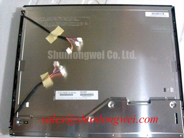
Begin with a cold mechanical inspection of the host enclosure. Confirm that the front opening does not load the active display area and that the bezel sits evenly around the perimeter. A rigid metal panel can transfer localized stress into the display assembly when the cabinet expands, contracts, or is tightened unevenly. The appropriate clearance is determined by the enclosure drawing, display outline, gasket design, and expected operating environment; it should not be inferred from the model number alone.
The stated mechanical installation consideration for this panel uses M3 fasteners at 0.35 to 0.45 N·m. This is a design consideration for chassis installation rather than a universal manufacturer guarantee for every host enclosure. Use a calibrated torque screwdriver and tighten in a cross pattern so the bezel is supported evenly. After fastening, inspect the display with a uniform test image and check for localized dark regions, optical mura, or brightness changes near the mounting points.
⚠ Safety Interlock Note: Disconnect the host equipment from its power source before removing or inserting the display cable, and allow the backlight supply to discharge according to the equipment service procedure.
Thermal expansion clearance should also be checked around cable exits and rear components. The panel must not be forced against a cabinet rib, cable clamp, or rear cover. If the enclosure uses a gasket, the compression profile should remain uniform without creating a concentrated load on one corner. Engineers evaluating another display in the same size class can use LQ9D03B as a reference for comparative mechanical and interface review, while confirming all dimensions from the applicable documentation.
Backlight control requires the same discipline. The supplied information does not establish a panel specific PWM frequency, dimming ratio, or backlight driver topology. If the SCADA console uses PWM brightness control, the integrator should verify the original controller requirements and evaluate frequency, duty cycle linearity, audible noise, and visible flicker at the complete system level. Do not assume that a host output designed for another display will be electrically compatible.
Industrial EMI Noise Immunity, Chassis Shielding Continuity and Common Mode Ferrite Chokes
During a replacement evaluation, inspect the complete signal path from the controller board to the panel. Pixel jitter, horizontal noise bands, intermittent image loss, or a white screen can involve cable routing, connector seating, impedance discontinuity, grounding, power integrity, controller timing, or the panel itself. These symptoms should be compared with a known good signal path rather than assigned to the panel without measurement.
The differential line impedance benchmark for the interface path is 100 Ω ±10%, identified as a design consideration. Where the host uses a differential display link, the engineer can verify the finished trace or cable assembly with suitable differential TDR equipment. The measurement should include the connector transition and cable interface where practical. An impedance mismatch may increase reflections and reduce timing margin, but the acceptance limit remains dependent on the transmitter, receiver, cable construction, and signaling standard used by the host.
Shield continuity should be examined around the full cable route. A shielded FFC or LVDS cable must be bonded according to the host equipment grounding architecture, with attention to connector shells, cabinet entry points, and areas close to high current switching conductors. A shield that is interrupted at the cabinet seam can allow common mode energy to couple into the display signal path. Ferrite components may be evaluated as a system level noise reduction measure when conducted or radiated interference has been identified, but their impedance behavior must be checked against the actual frequency spectrum and cable arrangement.
💡 Pro Tip: Keep the positive and negative members of each differential pair closely coupled and route them with matched path lengths, then verify clock and data quality at the receiver with an oscilloscope against the known good console signal.
For a high voltage substation protection and dispatch console, cable separation from contactors, inverter sections, relay wiring, and switching power supplies should be handled through the cabinet layout rather than by relying on the display module alone. The display is not independently certified for complete equipment EMC compliance. The finished console must be evaluated using the applicable system requirements and its actual enclosure, cable, grounding, and power arrangement.
The logic supply is specified as 3.3 V or 5.0 V ±0.5 V. Measure voltage at the panel connector while the display is operating, not only at the power supply output. Voltage drop through a long cable, connector resistance, or a shared load transient may create an abnormal operating condition. A white screen or logic failure can be associated with supply, reset, timing, or interface problems, so the diagnostic process should include connector inspection and signal comparison before replacing additional hardware.
Suppressing Acoustic Capacitor Buzz and EMI Emissions across PWM Frequencies
Backlight control must be identified from the original Sharp panel documentation and the host design. The supplied product data does not confirm whether this exact panel requires a particular CCFL circuit, LED driver, PWM input, analog dimming input, or integrated backlight arrangement. The system integrator should verify the required supply and control signals from the original panel documentation instead of applying a generic backlight controller.
If the host uses PWM dimming, the engineering evaluation should cover the complete path from the controller output to the backlight driver. The proposed test range may be selected by the system designer to examine audible components, visible flicker, camera banding, and electromagnetic emissions. The stated frequency range of 200 Hz to 1 kHz can be treated only as an evaluation range from the integration brief, not as an official specification of LQ190E1LW42. Duty cycle linearity should be measured at the displayed brightness levels required by the console operator.
Acoustic noise from capacitors, inductors, or switching assemblies should be investigated with the display installed in its final enclosure. A quiet bench result may change after the driver board is attached to a metal panel or adjacent to a cabinet surface that can amplify vibration. The diagnostic approach should correlate the sound with the backlight command, supply waveform, and switching activity. Do not treat audible buzz alone as proof of a defective LCD cell.
The product data gives a typical backlight lifetime of more than 50,000 hours, measured using an optical luminance photometer with the assessment based on maintaining more than 50 percent of initial brightness. This is an official typical specification for the stated backlight lifetime condition. It is not a guarantee of the service life of the complete console, power supply, driver, enclosure, or operating environment.
LVDS or TTL selection also requires documentation matching. The available product information does not define a specific JEIDA or VESA pixel mapping, transmitter clock rate, data hold time, or clock jitter limit for this page. The host engineer should confirm the panel interface standard, bit mapping, polarity, power sequence, and enable timing before powering the assembly. An image that appears scrambled, offset, or intermittently unstable may indicate a format or timing mismatch, so compare the controller configuration with the original display record.
The LM190E08-TLG6 page can be reviewed as a related display solution during system topology evaluation. It should not be treated as an automatic electrical substitute for this Sharp model. Connector pinout, backlight requirements, mounting details, and timing compatibility must be established independently for any related module.
High Nits Edge Lit LED Rail Thermal Dissipation and Light Guide Preservation
Inspect the rear of the installed display for contact with hot cabinet surfaces, power converters, or airflow restrictions. A display can experience a different thermal condition after installation because the enclosure changes convection and radiated heat paths. Any heat spreader or rail added by the system designer should support the intended mechanical structure without pressing on the panel or obstructing cable access.
The supplied specifications do not confirm a particular light guide material, edge rail construction, luminance rating, optical contrast ratio, or sunlight readability value for this model. Avoid assuming a PMMA light guide, a specific anti glare coating, or a direct sunlight contrast ratio without the original panel drawing or optical datasheet. If the console is installed near a bright window or outdoor substation control room, measure readability and luminance in the final viewing position rather than relying on a nominal display category.
Thermal verification should use the actual enclosure, backlight setting, controller load, and ambient conditions. Record temperature at representative external surfaces and compare the display image for gradual brightness nonuniformity, color change, or edge localized artifacts. A photometer can be used to assess luminance against the initial reference. The stated backlight lifetime condition is based on maintaining more than half of initial brightness and should not be reinterpreted as a guaranteed L70 or B50 rating for a separately designed LED rail.
For SCADA and protection consoles, the viewing function also depends on the host graphics controller. Confirm that the selected resolution, refresh behavior, pixel format, and scaling mode match the panel interface. If the display is being evaluated for a touch overlay, glove operation, or operation with water on the surface, those functions require separate verification because no touch sensitivity or touch controller specification is provided here. The same applies to cover glass, optical bonding, and anti glare performance.
Long duration validation should include repeated power cycles, backlight transitions, connector retention checks, image uniformity inspection, and supply measurement at the panel connector. The Industrial Display & HMI Solutions resource provides broader engineering context for industrial display integration, while the final acceptance criteria should remain tied to the host equipment requirements and the applicable Sharp documentation.