

Content last revised on September 29, 2026
Luminance Maintenance without Confusing EL Aging with LCD Degradation
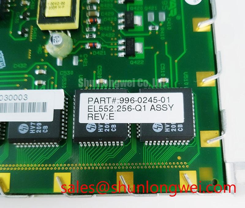
| Product model | EL552-256-Q1 |
|---|---|
| Manufacturer | Planar |
| Product category | Industrial display / HMI panel |
| Display technology | Electroluminescent (EL) panel |
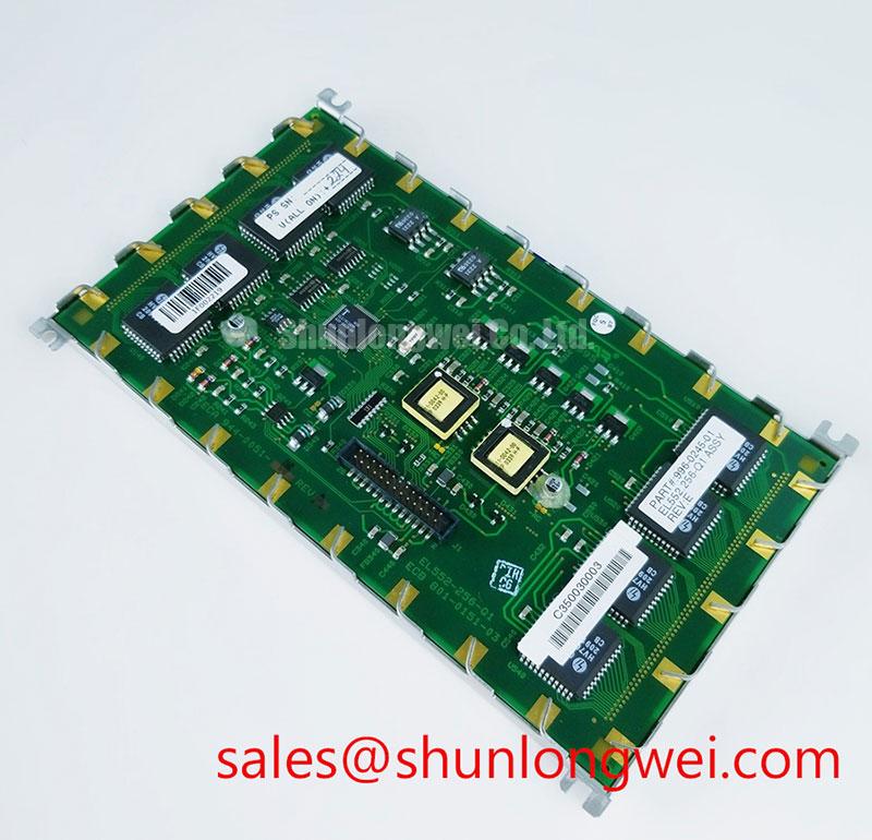
Display a uniform illuminated pattern on the EL552-256-Q1 and compare the center, edges, and corners under fixed ambient lighting. Record the controller configuration, displayed pattern, measurement position, and warm-up condition alongside each luminance reading. As a Design Consideration, this repeatable setup helps separate a panel-output change from differences caused by viewing geometry, front-window contamination, or the equipment’s brightness setting.
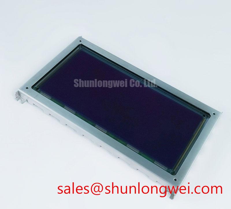
The important technology distinction is straightforward: this Planar electroluminescent panel is not a liquid-crystal display with a separate backlight. EL produces light through electrical excitation rather than by modulating a backlight through liquid crystal. LCD-specific explanations involving liquid-crystal freezing, backlight light-guide hotspots, or IPS viewing-angle compensation therefore do not describe this product. Incoming inspection should concentrate on emitted-image uniformity, pixel behavior, the external optical path, and the panel-to-controller connection.
Use the equipment’s supported diagnostic patterns to inspect fully illuminated areas, dark areas, alternating pixels, and fine lines. A fixed camera setup can document spatial differences, while a suitable luminance instrument provides a more useful comparison when brightness is the concern. Keep automatic camera exposure disabled during comparative photographs; otherwise, exposure compensation can conceal an actual output difference. These are Engineering Recommendations, not manufacturer acceptance limits for pixel defects or luminance variation.
Luminance half-life and mean time between failures describe different things. Half-life concerns a defined decline in emitted brightness under specified operating conditions; MTBF is a reliability statistic that depends on its calculation or test basis. Neither should be substituted for the other when deciding whether a display remains serviceable. A numerical lifetime, viewing-angle limit, cold-response time, or shock rating must come from a model-specific manufacturer specification, not from a general description of EL technology.
For an apparent brightness loss, compare the same image at the same brightness command and inspect the front window separately from the emitting surface. Surface deposits, a changed optical filter, controller settings, and electrical operating conditions can all influence the observation. A broad dim area does not establish a single cause. Correlate the optical result with controller behavior and repeat the test after correcting any accessible connection or optical-path issue.
As a Design Consideration, inspect mounting points for uneven loading, displaced hardware, and contact between the display assembly and surrounding metalwork. The mounting arrangement should accommodate the actual equipment’s vibration and shock requirements without stressing the panel. Hermeticity is a separate qualification question: visual inspection can reveal damage or contamination, but it cannot certify a seal. Any leak test requires an approved method and acceptance criterion for the particular assembly.
Dielectric Defect Screening without Assuming Self-Healing
Inspect a full illuminated field for persistent dark points, irregular bright regions, and intermittent rows, then repeat the observation with a different supported pattern. Note whether each feature remains at a fixed panel location or follows the image data. As a Design Consideration, that distinction helps organize subsequent checks without treating an optical symptom as proof of dielectric damage, a driver fault, or a connection failure.
Electrical excitation is central to EL operation, but the model designation does not establish the internal phosphor formulation, dielectric construction, drive-pulse amplitude, or charge-recovery circuit. Those details should not be inferred from another EL family. Likewise, a defect that appears stable during a brief inspection is not evidence that the panel has a guaranteed self-healing mechanism. Product acceptance should rest on documented criteria and repeatable measurements rather than an assumed microscopic explanation.
With the assembly isolated from its power source, examine accessible connectors for displaced contacts, damaged locking features, contamination, and cable strain. Use the equipment wiring diagram to identify the supply, return, and signal connections. Resistance measurements need interpretation in the context of the connected electronics: capacitors, protection networks, and driver circuitry can influence the result. A meter reading alone does not establish either a catastrophic short circuit or satisfactory dielectric integrity.
Bench Tip: Use ESD controls and isolate power before aligning the cable squarely and engaging its connector lock without forcing the contacts.
For powered investigation, use the approved controller and its specified operating conditions rather than an improvised excitation source. Any waveform measurement requires probe voltage capability, isolation arrangements, and a measurement reference appropriate to the circuit. As an Engineering Recommendation, compare the suspect assembly with a known-good signal path under matching conditions, paying attention to supply stability, waveform timing, and changes associated with the visible defect.
If the equipment documentation identifies an alternating drive waveform, assess its symmetry and offset against that documentation. Do not introduce an arbitrary drive-voltage range or a universal acceptable DC-offset limit. The controller architecture determines the relevant waveform and measurement location. The same boundary applies to insulation testing: an unsanctioned test voltage can exceed the limits of connected electronics even when the intention is simply to screen for leakage.
Record whether the controller enters protection, whether the supply behavior changes with the image pattern, and whether the defect remains after a controlled reconnection. These observations support a repair decision without claiming a particular internal failure mechanism. A repeatable anomaly warrants further evaluation against the original acceptance criteria; it does not justify assuming that the panel will repair itself during continued operation.
Connector Integrity, Image Timing, and Optical Test Interpretation
Trace an intermittent line or unstable image from the panel connector back to the controller while checking cable seating, contact condition, and the corresponding signal waveform. Separate a defect that occurs with a stationary cable from one that appears when cable position changes during a controlled inspection. As a Design Consideration, repeatable correlation is useful evidence, but it still requires electrical verification before assigning the fault to a contact or conductor.
The EL552-256-Q1 designation alone is not an interface specification. Establish the connector pinout, supply requirements, signal levels, data organization, and timing from the matching panel and controller documents. Do not treat LVDS, TTL, or a familiar connector outline as interchangeable interface descriptions. A connector that physically mates can still carry different signal assignments or require a different controller configuration.
Compare data and timing signals at the locations identified in the equipment schematic. Use probe arrangements that minimize disturbance to the measured circuit, and evaluate signal quality against the actual receiver requirements. Overshoot, ringing, timing variation, and supply disturbance can be relevant to unstable image behavior, but their allowable limits belong to the documented interface. Cable impedance and termination should follow that interface rather than a generic display-cable prescription.
For symptoms associated with nearby switching equipment, compare operation under controlled equipment states and inspect cable routing, shield connections, and return paths. As an Engineering Recommendation, make one reversible change at a time and retain the same diagnostic image. This helps establish whether interference is correlated with the symptom. It does not establish that the panel independently meets a complete machine’s EMC requirements; that assessment belongs to the integrated equipment.
Optical interpretation also needs the correct technology boundary. The discussion of Gamma Correction and Non-Linear Display Tone Reproduction explains why encoded image values and displayed brightness need not have a linear relationship. It does not establish that this Planar model contains an LCD-style gamma-voltage ladder or supports a particular grayscale implementation. Use only diagnostic levels and brightness controls supported by the installed controller.
For comparison with other display architectures, The Ultimate Guide to Industrial TFT LCD Technology provides background on TFT terminology and integration questions. Keep its backlight, liquid-crystal, and timing-controller explanations separate from EL-specific fault assessment. That distinction prevents a technician from spending time checking an LCD subsystem that is not part of the display technology identified here.
Complete the signal inspection by restoring the cable routing and strain relief, then repeating the image-pattern test. Document the controller revision and any configuration changes alongside the result. An image that becomes stable after reseating is useful evidence of a connection-related issue, but continued stability under the equipment’s normal operating conditions is a separate verification task.
Replacement Fit and Marine Console Compatibility Assessment
Compare the EL552-256-Q1 assembly’s mounting locations, visible aperture, connector position, and cable clearance with the equipment drawing before releasing a replacement for installation. Match the complete model designation and controller requirements rather than interpreting the digits in the part number as a confirmed resolution. As a Design Consideration, mechanical fit and electrical compatibility are separate checks; passing one does not establish the other.
A replacement assessment should retain the original display’s functional requirements: image format, readable area, brightness control, controller communication, and startup behavior. Dimensions and mounting tolerances require the applicable mechanical drawing. Supply and timing requirements require the electrical documentation. Record these checks explicitly so that procurement and repair teams can distinguish a verified fit from a candidate that still needs equipment-level evaluation.
The LM238WF4-SSF1 is a separate display product that may appear during a broader sourcing review; the link does not establish compatibility with the Planar EL552-256-Q1. A different display technology or assembly requires its own mechanical, electrical, optical, and controller assessment. It should not be presented as a same-size or same-resolution replacement without evidence supporting those specific claims.
Marine radar and navigation bridge consoles are potential equipment contexts for compatibility evaluation, not a statement of this panel’s marine qualification. For such an installation, assess readability through the actual protective window, performance under the console’s ambient illumination, and the effect of any optical filter. Outdoor visibility cannot be established from the word “electroluminescent” alone. The assembled console’s optical path and operating conditions determine the practical result.
As an Engineering Recommendation, examine the enclosure gasket, window attachment, cable entry, and evidence of moisture or salt contamination independently of the display. Panel technology does not certify enclosure sealing or corrosion resistance. Optical bonding, if included in an equipment redesign, introduces its own compatibility and serviceability questions; it should not be assumed to be an existing feature of this model.
After installation, reproduce the supported diagnostic patterns with the enclosure assembled and the original cable restraint restored. Check that the bezel does not obscure the active image, that mounting loads have not introduced a visible change, and that brightness control behaves consistently. Preserve the inspection record with the exact panel designation, controller configuration, optical observations, and unresolved acceptance items so the equipment engineer can authorize return to service on documented evidence.