

Content last revised on November 18, 2026
Benchtop Waveform Tuning: Mitigating Stress via Common-Mode Transient Immunity on CM150TX-24S
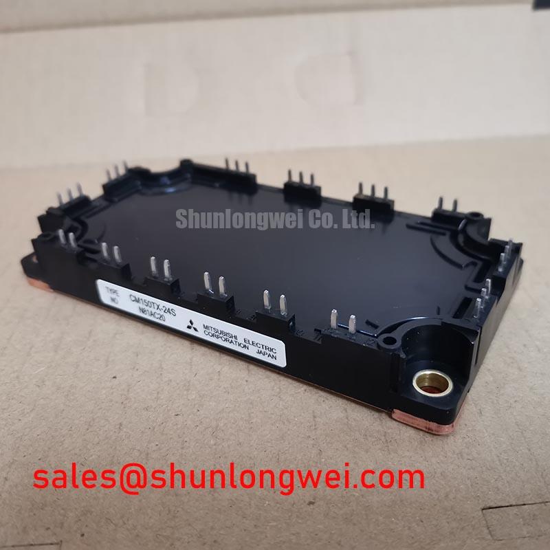
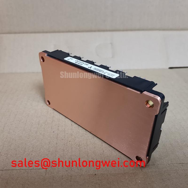
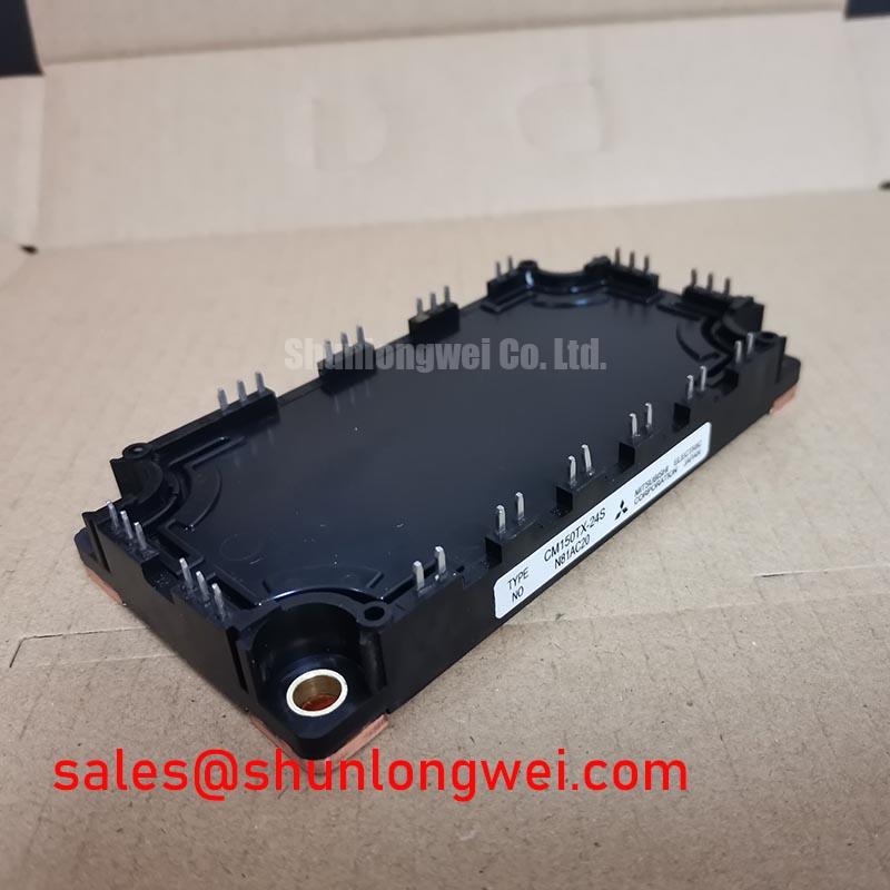
Manufacturer: Mitsubishi Electric | Part Number: CM150TX-24S | Collector-Emitter Voltage (Vces): 1200.0 V | Continuous Collector Current (Ic): 150.0 A | Package: Module | Configuration / Topology: IGBT Power Stage | Consult the manufacturer datasheet for rating conditions, terminal assignments, and mechanical limits.
I check the gate waveform against its local emitter reference before treating an unexpected switching pulse as a defective CM150TX-24S. With the equipment isolated and the DC link verified discharged, I first establish the terminal mapping from the circuit drawing. Cold resistance comparisons between equivalent circuit positions can identify suspicious asymmetry, but parallel components and connected drivers can influence the readings. An isolated measurement is more useful than a verdict based on an unexplained meter value.
Design Consideration: During controlled switching tests, capture the driver input, gate-to-emitter voltage, and switching-node transition together. A pulse appearing at the driver output without a corresponding input command warrants investigation of the isolation interface, driver supply disturbance, and measurement arrangement. Gate movement coincident with the opposite switch transition can also involve capacitive coupling or shared emitter inductance. These observations distinguish investigation paths; none establishes a single cause by itself.
Common-mode transient immunity belongs to the selected gate-driver isolation system, not to the module’s collector-emitter rating. Likewise, reinforced insulation requires evidence for the complete barrier arrangement and applicable equipment requirements. Assess the isolator, isolated power supply, PCB separation, connector spacing, and contamination together. Do not transfer a driver’s isolation claim to the power module or infer an insulation classification from 1200.0 V.
Keep the gate drive and its return closely associated, away from high-current switching paths. Where the documented terminal arrangement provides a separate gate-reference return, preserve that separation through the driver connection; do not assume an undocumented auxiliary emitter terminal exists. Check clearance and creepage against the equipment’s working voltage, environment, and applicable standard rather than selecting spacing from the module rating alone.
Field Alert: Verify DC-link discharge before moving gate connections or attaching probes, and use a measurement arrangement rated for the actual circuit potential.
Field Diagnostics & Commissioning: Junction-to-Case Thermal Network Simulation in CM150TX-24S Topologies
Record the overload pulse duration, repetition pattern, case temperature, and operating current before estimating junction-temperature rise. A heatsink reading taken after a trip cannot reconstruct the junction peak during a short overload. For the CM150TX-24S, the useful commissioning record connects the electrical event to the thermal starting condition, including whether the assembly was already warm from preceding operation.
Design Consideration: Use the manufacturer’s transient thermal impedance information to evaluate pulsed loading. When an appropriate multi-RC model is supplied or fitted to those curves, apply the time-dependent device losses and retain the thermal history between pulses. An Engineering Calculation of junction temperature combines the measured case-temperature boundary with the modeled junction-to-case rise. Report the model basis and loss assumptions alongside the result; an arbitrary RC network cannot establish a product-specific temperature margin.
Check the physical heat path before adjusting protection settings. Inspect the mating surfaces for damage, confirm that the assembly sits without mechanical rocking, and apply the specified thermal interface and fastening procedure. Uneven contact can complicate interpretation of case measurements. Treat the 150.0 A continuous collector-current specification as a rating with defined conditions, not as permission to reproduce that current under any cooling arrangement.
Desaturation protection needs its own timing capture. Observe the gate command, collector-emitter voltage, sensing-node behavior, and shutdown response during a controlled protection test. The blanking interval must reject the normal turn-on transition while allowing the complete protection chain to act within the device’s documented short-circuit capability. A universal detection delay is inappropriate: sensing, filtering, driver propagation, and turn-off all consume the available interval.
If the driver implements two-stage soft turn-off, evaluate both the initial current reduction and final gate discharge. Excessively abrupt interruption can increase voltage overshoot, while excessive slowing extends fault energy. Set that balance using the device’s supported operating boundaries and measured waveforms. Normal on-state Vce(sat) behavior and a desaturation fault threshold serve different purposes and should not be treated as interchangeable specifications.
Benchtop Waveform Tuning: Mitigating Stress via Drop-In Retrofit: Tuning Turn-On/Turn-Off on CM150TX-24S
Compare the replacement assembly’s terminal drawing, mounting geometry, and gate-driver connections before retaining the legacy board’s gate-resistor values. A matching current and voltage label does not establish a drop-in replacement. For procurement, record the exact CM150TX-24S designation, terminal orientation, mechanical interfaces, and required supporting documentation against the removed assembly and equipment bill of materials.
Engineering Recommendation: Treat the existing turn-on and turn-off resistors as evaluation inputs rather than approved settings. Where the driver provides separate charging and discharging paths, assess their effects independently. Changing turn-on resistance affects switching transition speed, commutation behavior, and switching loss; changing turn-off resistance affects the current fall and associated overshoot. Select the final arrangement from measured behavior across the intended operating conditions and the driver’s output capability.
Capture gate-to-emitter voltage at the module connection rather than relying solely on the driver-board test point. Interconnect inductance can make the two waveforms differ. Keep probe connections compact, check probe compensation and bandwidth suitability, and compare repeatable captures under equivalent conditions. A ringing trace that changes substantially when the probe arrangement changes deserves a measurement review before a component change.
During commutation testing, examine the circuit’s freewheeling-diode recovery together with collector current and voltage. Reverse-recovery shape can influence ringing and conducted or radiated disturbance, but a softness factor requires defined recovery intervals and test conditions. Do not assign a recovery-softness value to this module from waveform appearance alone. Equipment-level emissions compliance also requires assessment of the assembled system, including cabling, enclosure, grounding, and filtering.
If the repair materials list also includes CM150DC1-24NFM, use it as a separate comparison entry, not an assumed compatible substitute. Check topology, pin assignments, switching characteristics, protection compatibility, and mounting details before considering an exchange. For a heavy-duty variable-frequency AC motor drive evaluation, these checks should include the existing inverter arrangement and commissioning procedure rather than only the headline ratings.
CM150TX-24S Operational Boundaries: Evaluating Overvoltage Trip Prevention and Fast-Switching Limits
Capture the DC-link voltage through the deceleration event before changing an overvoltage trip setting. Establish whether the rise follows regenerative energy returning from the load or appears as a brief local switching transient. Those conditions require different investigations: a braking circuit manages returned energy, while switching-loop layout and commutation behavior affect local overshoot. Increasing a trip threshold does not resolve either mechanism.
Design Consideration: Identify the installed braking circuit from the equipment schematic, including its switching device, resistor connection, control signal, and protective interlocks. The supplied IGBT Power Stage classification does not establish that the CM150TX-24S contains a dedicated braking switch. Evaluate any braking IGBT against its own voltage, current, thermal, and switching limits, then check that its control arrangement responds appropriately during regeneration.
Size or reassess the braking resistor from the energy returned during the actual deceleration profile and the repetition of that event. Resistance affects braking current when the chopper conducts; pulse-energy capability, average dissipation, cooling, and temperature protection address different stresses. A resistor selected only by its continuous wattage can leave the pulse-loading question unresolved. The equipment designer should determine acceptable values from the motor-load behavior, chopper limits, and resistor manufacturer’s pulse-loading information.
Inspect braking-path terminals and wiring with power isolated, then correlate the chopper command with DC-link response during controlled commissioning. An absent command, an interrupted power path, or thermal protection activity can produce overlapping symptoms. Verify each against the circuit rather than assigning every deceleration trip to the module. Maintain the specified separation around high-voltage terminals and avoid routing braking-current conductors alongside sensitive gate-drive references.
For background on switching stress and power-conversion tradeoffs, the IGBTs in High-Power SMPS Engineering Guide provides supporting engineering context, not a replacement for equipment acceptance limits. Finish the deceleration test by recording peak DC-link voltage, local collector-emitter overshoot, braking activity, and temperature behavior against the approved operating envelope, including repeat events from a warm starting condition.