



Content last revised on September 12, 2026
Sharp LQ190E1LW01 Inspection and Compatibility
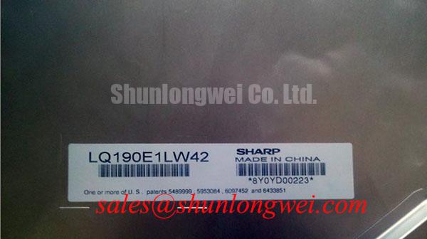
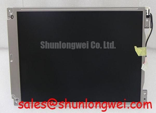
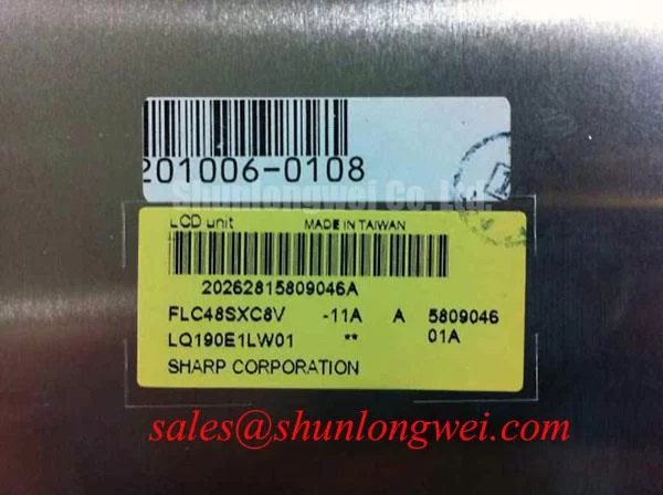
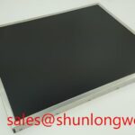
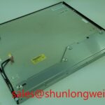
Start the bench inspection by checking the Sharp LQ190E1LW01 label against the equipment service record, then examine the connector, glass edges, frame, and visible surface for handling damage before applying power. This panel is identified in the supplied factory context as an Industrial Grade LCD/HMI Panel in a TFT LCD display module format. The available specification set confirms the manufacturer, product category, package description, and official factory specification status, but it does not confirm the panel resolution, brightness, viewing angle, interface pinout, supply voltage, backlight technology, or mechanical drawing. Those values should be taken from the original Sharp documentation or the display assembly already installed in the equipment.
| Item | Confirmed information |
|---|---|
| Model | LQ190E1LW01 |
| Manufacturer | Sharp |
| Product category | Industrial Grade LCD/HMI Panel |
| Construction description | TFT LCD Display Module |
| Specification status | Official Factory Spec Verified |
For overseas repair teams, the most important first decision is interface compatibility rather than visual similarity. A panel that appears to have the same diagonal size can still fail at the electrical, timing, connector, mounting, or backlight level. Record the original panel’s connector orientation, cable keying, mounting-hole pattern, active-area position, bezel opening, and controller settings before approving a replacement. If the documentation does not identify a value, do not treat a common LCD convention as confirmation for this model.
TN Display Characteristics and Viewing Direction Alignment
The normally white TN description should be verified from the original panel documentation before it is used to define an optical acceptance test. TN displays can show viewing-direction-dependent grayscale behavior, particularly when the operator views the screen from above, below, or an oblique side angle. This matters in a navigation bridge console because the display may be read while the operator is standing, seated, or looking across the instrument panel. A replacement should therefore be evaluated in the actual enclosure position, with the intended text, radar trace, alarm colors, and low-level grayscale patterns visible from the working position.
Do not substitute an IPS or MVA viewing-cone assumption for this Sharp module. The supplied product context does not provide a confirmed four-direction viewing-angle specification, and no numerical optical cone should be attributed to the LQ190E1LW01 without a datasheet. The system integrator should compare the original and replacement panels using identical image settings, ambient lighting, and observer positions. The check should include dark gray transitions, colored symbols, thin lines, and the lowest contrast elements used by the host application.
Surface reflection is a separate issue from grayscale inversion. In bright marine environments, glare can conceal information even when the panel electronics and backlight are operating correctly. Inspect the existing cover glass, optical film, and bezel geometry as an assembly. An anti-glare surface may reduce specular reflections, but it can also alter perceived sharpness, black level, or fine-line clarity. The LQ190E1LW01 specification set supplied here does not confirm an anti-glare treatment, contrast ratio, or sunlight readability rating. These characteristics should be verified against the original assembly or measured under the equipment’s intended lighting conditions.
For a high-EMI control cabinet, the display cable should be routed as a controlled differential interface where the host documentation requires it. Minimize the cable loop area, maintain a continuous reference plane, and keep high-current switching paths away from the display harness. Any target differential impedance and allowable skew must come from the controller, cable, and panel interface documentation as a combined design requirement. If a new cable or adapter is introduced, compare the eye quality and pixel stability with an oscilloscope against a known-good installation.
Mechanical Stress and Glass-Substrate Damage Prevention
Mechanical inspection should begin before the panel is fitted into the console. Check the glass perimeter, frame seating, connector reinforcement, flexible cable transitions, and the contact points created by the enclosure. A panel can show an intermittent line or color region when the display assembly is exposed to uneven frame pressure, cable bending, vibration, or repeated service access. The available factory data does not document internal driver-bump construction or provide a field failure rate, so a visible symptom should be recorded and investigated rather than assigned to a single internal cause.
A practical bench sequence uses three primary-color screens followed by a neutral grayscale image. Display red, green, and blue test fields at stable brightness, then inspect the panel from the normal operating direction and from a shallow angle. Look for a line, block, color shift, flicker, or area that changes when the signal source, cable seating, or enclosure pressure changes. This sequence helps separate repeatable image-path behavior from a defect that appears only under a particular color channel, although it cannot by itself identify the failed component.
A flashlight held at approximately forty-five degrees can provide a useful dark-shadow check when the screen appears unlit. If the image can be seen in the reflected or shadowed area, the video path may still be active while the backlight or its power path requires investigation. If no image is visible, verify the host controller output, panel power, enable state, cable continuity, and connector seating before evaluating the glass assembly. This is a diagnostic method, not a model-specific failure threshold.
💡 Pro Tip: Support the display frame evenly during installation and disconnect all power before inserting or removing the panel cable.
When a line defect remains after cable and controller checks, inspect whether it is fixed at the same glass position across every test image. A stable position can justify further panel-level evaluation, while a symptom that follows a cable movement or input configuration should keep the interface and mechanical installation in scope. Avoid pressing the glass or flexible edge to reproduce a fault; that action can create additional mechanical stress and compromise the evidence needed for a controlled repair decision.
For a marine console, enclosure sealing and service access should also be reviewed. Salt-laden air, condensation, and cleaning fluids can affect connectors and optical surfaces even when the display itself is rated for industrial use. The supplied data does not establish an ingress rating, corrosion qualification, or marine certification for this model. Those requirements belong to the complete display assembly and enclosure, and should be assessed separately by the equipment designer.
Connector, Interface, and Timing Verification
The connector count must be verified from the original panel drawing rather than inferred from the model family. A twenty-pin or thirty-pin appearance does not establish the signal assignment, lane count, unused pins, backlight pins, or power pins. Before connecting the LQ190E1LW01, photograph the original cable and record its key position, pin-one orientation, wire colors, shielding arrangement, and mating connector. The system integrator should verify the required supply voltage from the original panel documentation.
Power sequencing deserves the same attention as signal mapping. Confirm the host’s panel supply, ground return, display enable behavior, reset requirements, and backlight enable sequence from the equipment schematic. The prompt-supplied product data does not confirm whether this model accepts a particular logic supply, nor does it provide a power-on rise-time limit. A controller configured for another panel can produce a blank screen, unstable startup, or abnormal current draw even when the connector appears mechanically compatible.
LVDS data format must also be checked. JEIDA and VESA mappings can place color bits in different positions, and a mismatch may appear as incorrect colors, split-screen content, mirrored data, or unstable imagery. Verify the required mapping, pixel order, lane polarity, clock polarity, and timing values from the original documentation. If the host supports multiple panel profiles, load the profile associated with the documented Sharp module and compare the result with the removed panel before changing unrelated display settings.
Use a short, correctly shielded cable path and maintain a continuous reference path around high-speed pairs. The design objective is to preserve pair balance and signal integrity through the connector, adapter, and harness. Differential impedance targets, pair skew limits, and clock-to-data timing margins are system requirements that must be confirmed with the panel and controller documentation; they are not official LQ190E1LW01 specifications in the information supplied here. During validation, inspect the differential waveform, common-mode behavior, eye opening, and error symptoms while the adjacent inverter, motor drive, or switching converter operates in its normal state.
For possible same-size or same-resolution sourcing work, engineers may evaluate LM190E08-TLG6 as a separate display option. That link does not establish drop-in compatibility with the LQ190E1LW01. Resolution, connector assignment, timing, optical stack, mounting geometry, and backlight control still require a line-by-line comparison before any substitution is approved.
When the panel is installed behind a protective window, check the bezel opening and viewing direction with the complete mechanical stack assembled. The supplied data does not verify a contrast ratio under direct sunlight or a specific anti-glare coating. A sunlight test should use the actual window, hood, ambient reflections, image content, and brightness control used by the equipment. If the marine radar console depends on low-level echoes or fine navigation markings, evaluate those functions rather than relying only on a white test screen.
Backlight and Insulation Testing
Do not assume that the LQ190E1LW01 uses a CCFL backlight, an LED backlight, or a particular high-voltage ignition arrangement from the model number alone. The supplied factory context identifies a TFT LCD display module but does not state the backlight type, lamp voltage, LED current, dimming interface, insulation rating, contrast performance, or lifetime value. The original panel documentation and the installed backlight driver determine the correct test method.
If the original assembly uses a high-voltage lamp circuit, insulation testing must be performed by qualified personnel with the panel disconnected from sensitive electronics and with the driver manufacturer’s limits observed. Inspect the secondary cable, transformer area, connectors, insulation barriers, and chassis clearances. A high-voltage test instrument should never be connected to an unverified panel pin simply because it resembles a lamp output. The applicable test voltage, duration, and acceptance criteria must come from the relevant assembly documentation and safety procedure.
If the assembly uses an LED backlight, inspect the constant-current driver, enable line, dimming signal, current feedback path, and thermal condition. PWM dimming frequency and duty-cycle behavior are controller-level choices unless the panel documentation specifies them. A proposed control range such as two hundred hertz to one kilohertz should be treated as a system evaluation range only, with flicker, camera interaction, acoustic behavior, and low-duty brightness tested in the completed console. It should not be presented as an LQ190E1LW01 factory rating.
Backlight open-circuit and short-circuit protection should be evaluated at the driver output. During a controlled test, monitor whether the driver limits current, shuts down, retries, or reports a fault when the load is disconnected or abnormal. Use the driver’s documented protection behavior to interpret the result. A dark panel may involve the backlight, enable signal, supply rail, cable, controller, or image path, so the diagnostic record should include each observation rather than assigning the symptom to one cause.
LED efficiency, thermal drift, and long-term brightness reduction depend on the complete optical and electrical assembly. The supplied information does not support a specific five-thousand-hour or fifty-thousand-hour MTBF claim for this Sharp model, and no field-life percentage should be attached to it. Designers seeking extended service operation should define an acceptance test for brightness, color, startup behavior, dimming stability, and enclosure temperature, then verify the results against the equipment requirement and the original panel documentation.
For a broader system-level review covering industrial display integration and environmental considerations, see Industrial Display & HMI Solutions. In a console architecture where the display depends on a separate backlight or interface-support assembly, engineers can also review LMS700KF01-001 as a distinct peripheral display solution. Neither reference replaces the electrical and mechanical compatibility checks required for the Sharp LQ190E1LW01 installation.