

Content last revised on October 8, 2026
Display Interface Synchronization & Logic Power Rail Verification
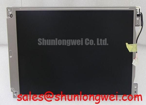
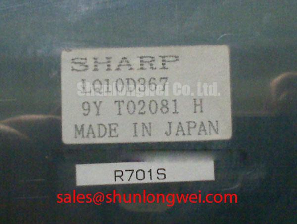
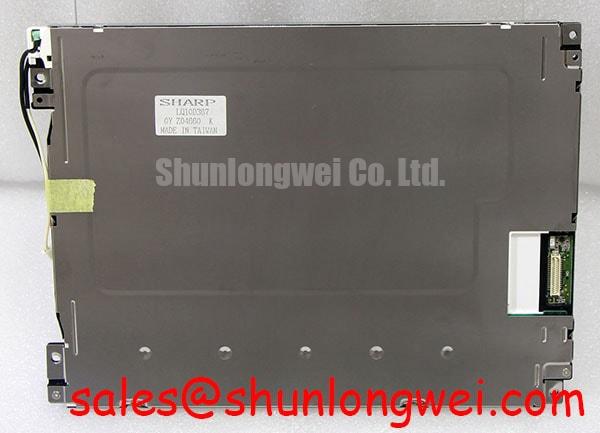
Disconnect the display harness with equipment power isolated, then compare the Sharp LQ10D367 label, connector orientation, and mounting arrangement with the original display assembly before applying power. For an AGV operator panel or forklift telematics terminal, this first check helps prevent a mechanically similar display from being connected to an electrically incompatible controller. The product is a TFT-LCD display module; its interface and electrical limits must be established from the model-specific documentation before integration.
| Product identification | Specified information | Integration significance |
|---|---|---|
| Model | LQ10D367 | Match the complete designation against the installed assembly and equipment documentation. |
| Manufacturer | Sharp | Use documentation corresponding to this manufacturer and model. |
| Product category | LCD display module | Evaluate within the complete display enclosure and controller system. |
| Module form | TFT-LCD display module | Confirm mounting, electrical connection, illumination, and image timing separately. |
A TTL digital RGB bus should not be assumed solely from the module designation. Parallel RGB and LVDS use different electrical signaling, and the differential termination practices associated with LVDS do not automatically apply to a parallel TTL connection. Likewise, JEIDA and VESA mapping are relevant only when the actual interface implementation requires them. Treat a TTL RGB interface as a verification topic, not as a confirmed LQ10D367 specification.
Design Consideration: Trace the installed signal path from the host graphics controller through any conversion board to the panel connector. Identify the clock, data, synchronization, enable, and return connections using the equipment schematic. If a conversion board is present, distinguish its input format from its panel-side output; a host connector does not establish the electrical interface at the display itself.
The required logic voltage, supply tolerance, power sequencing, and permissible rise time should come from the original panel documentation. Do not select a supply voltage by connector appearance or by comparison with another Sharp display. During bench verification, observe the supply at the panel connection as well as at the regulator, since harness resistance and connector condition can make those measurements differ under load. Check signal activity against the documented power sequence rather than imposing a generic startup delay.
For synchronization faults, inspect the clock and associated data at the receiving end using a measurement method appropriate to the confirmed interface. A split image or unstable picture may involve timing, mapping, connector continuity, or controller configuration. Compare the signal path with a known-good assembly before changing termination or firmware settings. Impedance targets, skew limits, and clock margins remain system-specific until the panel and interface-board requirements are established.
Backlight Thermal Dissipation & Optical Assembly Preservation
Inspect the illumination assembly and enclosure heat path before specifying a backlight driver or modifying cooling. The LQ10D367 identity alone does not establish high-brightness operation, edge-lit LED construction, or a PMMA light guide. Those descriptions must not become purchasing requirements or maintenance assumptions without matching documentation. Identify the actual illumination arrangement, its electrical connections, and any separate driver before investigating brightness loss.
Design Consideration: In an AGV or forklift enclosure, evaluate heat from the host electronics, illumination system, and surrounding equipment together. A sealed housing can reduce dust entry while restricting heat removal. Any added heat spreader should contact a suitable structural surface, maintain required electrical clearances, and preserve the panel’s permitted mounting arrangement. Its dimensions and attachment method should be determined from the enclosure geometry and measured thermal behavior, not from a generic display rule.
Examine perimeter seals for hardening, displacement, and contamination. Oil residue or compressed debris around the bezel can interfere with seating and create uneven mechanical loading. Cleaning materials should be selected against the documented surface and gasket compatibility. Do not assume that a solvent suitable for the metal housing is acceptable for the display surface, protective window, or adhesive joints.
⚠️ Maintenance Note: Inspect vibration pads and perimeter seals during scheduled service, and replace deteriorated parts to the equipment specification rather than tightening the bezel to compensate for lost support.
Cold-start behavior also needs a system-level check. Liquid-crystal response can change with temperature, but a specific response-time limit or sub-zero operating capability cannot be assigned to this module without its temperature ratings. If equipment moves between a cold storage area and a warmer loading zone, assess condensation at the window, connector, and enclosure surfaces before energizing the display. Any heater arrangement should be evaluated against the verified module limits and enclosure requirements.
For illumination complaints, separate optical obstruction from electrical drive and temperature effects. Observe whether reduced brightness is uniform, localized, or dependent on warm-up, then check the appropriate driver output and connector condition. A dark region does not establish a particular internal material failure. Similarly, LED lumen-maintenance classifications do not establish the operating life of an entire display assembly. Lifetime claims require applicable manufacturer data and stated test conditions.
When reviewing a different display architecture, the LM64P10 provides a separate model reference whose controller and illumination requirements must be assessed independently. It should not be treated as a backlight driver, accessory, or electrically compatible companion for the LQ10D367 without supporting documentation.
Diagnosing Pixel Jitter & Horizontal White Lines Near 400 V Motor Drives
Record when the image disturbance occurs before changing the display harness. On equipment operating near a motor drive, compare the picture with the drive idle, switching, accelerating, and under its normal load. An association with a nearby 400 V drive is a diagnostic clue, not proof that the display has failed or that radiated interference is the only cause. Supply disturbance, grounding, cable movement, and controller timing can produce overlapping symptoms.
Design Consideration: Inspect the actual cable construction before proposing shielding changes. A flexible printed cable, a shielded harness, and an LVDS cable assembly require different termination and routing assessments. Maintain the signal-return arrangement intended by the equipment design, and examine shield connections where a shield is actually provided. A chassis connection should not be added indiscriminately to a signal return or connector pin.
Follow the harness through the enclosure and look for proximity to switching conductors, damaged strain relief, unsupported bends, and movement at connectors. Where the equipment layout permits, separating display wiring from motor power wiring can be evaluated as a corrective measure. Confirm the result under representative operating conditions rather than assuming that a routing change has resolved every interference mechanism.
Ferrite suppression is also a conditional measure. Its suitability depends on the noise path, frequency content, cable arrangement, and effect on the intended signal. Establish whether the disturbance appears on the supply, signal reference, or communication path before selecting a suppression component. A ferrite added without this distinction can obscure the diagnosis or affect interface behavior without addressing the underlying coupling.
Clock jitter and data hold-time checks must use the limits for the confirmed panel interface and controller. Probe at the relevant receiving point, account for the measurement setup, and compare behavior during both quiet and disturbed operation. For a differential link, inspect the pair as a differential signal; for a parallel bus, evaluate the clock and data relative to their intended return. Neither a universal skew budget nor a generic termination value establishes compatibility.
If noise bands persist with the drive inactive, inspect the controller supply and documented timing-controller connections before attributing the fault to electromagnetic interference. Where accessible and documented, grayscale reference measurements should be compared with service limits or a known-good board. The The Ultimate Guide to Industrial TFT LCD Technology provides broader context for distinguishing interface, illumination, and optical faults; it does not replace the LQ10D367 electrical specification.
Grayscale Inversion Mitigation & Optimal Viewing Direction Alignment
Check image readability from the actual operator position before approving a display installation. A forklift terminal may be viewed from a seated position while an AGV service panel may be read from above or beside the enclosure. These are integration conditions to assess, not evidence that the LQ10D367 has been qualified for either application. Its liquid-crystal mode, normal optical state, preferred viewing direction, and viewing-angle limits require model-specific confirmation.
If the original documentation specifies a preferred viewing direction, align the panel accordingly and assess the completed assembly with its protective window installed. Color and contrast changes with viewing position should be distinguished from defects visible at all angles. A panel technology comparison cannot establish compatibility by itself.
Design Consideration: Test readability using the equipment’s actual alarm colors, small text, shaded controls, and status graphics. Include the ambient lighting encountered during normal operation. Reflections from the enclosure window may dominate readability even when the panel is functioning correctly. Confirm any anti-glare treatment from the applicable documentation rather than assuming an etched surface or applying an unapproved film.
For grayscale complaints, first check host color settings, conversion-board configuration, and the documented signal mapping. Where a timing controller exposes serviceable gamma references, compare them using the equipment’s approved diagnostic procedure. Do not adjust internal reference voltages simply to compensate for an unfavorable viewing angle. Uneven gray transitions can involve configuration, reference circuitry, supply behavior, or the optical assembly, so measurements should precede component replacement.
Dimming behavior must be assessed against the actual illumination driver. Confirm whether brightness control is supported, which control input is used, and what operating limits apply. A generic PWM frequency or duty-cycle range is not an LQ10D367 specification. If flicker or audible noise appears during adjustment, observe the control signal and driver behavior while checking the permitted settings; do not assume that increasing frequency is an acceptable remedy.
For replacement screening, compare the LQ10D367 with another display only after establishing the original resolution, active area, outline dimensions, connector assignment, interface timing, illumination requirements, and mounting points. The LM190E08-TLG6 is a separate selection reference, not a confirmed same-size or interchangeable replacement. Procurement should request the relevant dimensional drawing and electrical specification for each candidate, while maintenance should verify window alignment, harness reach, enclosure sealing, and operator visibility before releasing the repaired terminal.