

Content last revised on October 18, 2026
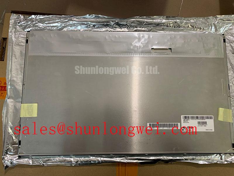
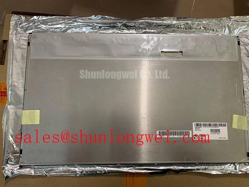
LM215WF3-SLK1 LG Display TFT-LCD Active-Matrix Color Display Module
When a substation protection console shows a persistent vertical line, begin with a full-screen primary-color test and inspect the panel while the display is operating under controlled illumination. The LM215WF3-SLK1 is an LG Display TFT-LCD active-matrix color display module. The available product classification does not establish a universal supply voltage, current rating, resolution, viewing technology, or backlight specification, so the original panel documentation and host display controller remain the controlling references.
For replacement planning, match the original panel’s mechanical envelope, connector orientation, signal format, backlight arrangement, and power-sequencing requirements before installation. An apparently compatible panel can otherwise produce white-screen startup, unstable synchronization, or residual images during power removal.
In a high-voltage substation protection or SCADA dispatch console, the panel should be assessed as part of the complete display chain. Check the controller output, cable routing, backlight driver behavior, chassis pressure, and environmental light conditions together. A same-size reference such as LM201W01-SLA1 may assist a neutral comparison exercise, but interchangeability still depends on the host system and the original panel interface.
Single Vertical Hairline Defect & Sub-Pixel Column Driver Open-Circuit Localization
Use a three-stage primary-color sequence to determine whether a single vertical hairline remains fixed across red, green, and blue screens. A defect that follows the same column position across all colors deserves closer attention at the panel edge, flexible connection, and column-driver region, while a line that changes with image content should be assessed alongside the controller signal and timing path.
Dim the surrounding room lighting, display a uniform field, and place a flashlight at approximately 45 degrees to the front surface. The resulting dark-shadow contrast can help separate a surface reflection or backlight irregularity from a line-forming display defect. Avoid pressing the glass or bezel during this check because mechanical pressure can temporarily alter an edge connection and create a misleading result.
Direct sunlight can reduce the visibility of a narrow defect and distort visual judgment. A stated contrast target above 500:1 at 50,000 lux should not be assigned to this model without an applicable manufacturer specification; it is better treated as a Design Consideration for the test environment. Anti-glare behavior should also be judged from the installed viewing position, since surface reflections can resemble uneven luminance or a missing sub-pixel column.
For incoming QA, record whether the line is continuous, intermittent, color-dependent, or affected by chassis movement. Compare the display with a known-good signal path before attributing the symptom to a column-driver open circuit. 💡 Bench Tip: Use ESD protection and keep the FPC fully parallel to the connector before closing its lock; never insert or remove the display cable while the system is energized.
Long-term static SCADA graphics also warrant a controlled image-retention check. Rotate high-contrast screen elements during evaluation and inspect the panel after normal content returns, without labeling temporary persistence as permanent burn-in until the complete display assembly has been assessed.
Aluminum Heat Spreader Sizing & Thermal Interface Placement along Narrow Display Edges
Place any edge heat-spreading rail so that it supports the chassis thermal path without touching the active viewing area, glass perimeter, flexible circuits, or optical layers. The thermal objective is to reduce localized hot spots rather than force heat into a neighboring edge. The panel’s actual construction and approved mounting method should govern the final rail geometry.
An aluminum rail may be considered where a controller board, backlight interface, or enclosed cabinet creates a concentrated heat source near a narrow display edge. This remains a Design Consideration, not an LM215WF3-SLK1 factory rating. The interface should be continuous enough to transfer heat while avoiding point loading, abrasive contact, and compression that could produce visible mura or stress marks.
Backlight control must be checked at the complete system level. A PWM dimming range of 200 Hz to 1 kHz can be used as a Design Consideration during bench evaluation for audible interaction, camera banding, and visible flicker, but the host driver and panel documentation determine acceptable operation. Observe text edges, gray ramps, and moving cursor lines at several brightness settings rather than relying on a single white test screen.
Duty-cycle linearity is important in an HMI because uneven brightness steps can be mistaken for panel aging or thermal nonuniformity. Measure the displayed luminance response after the enclosure reaches its normal thermal condition. If a heat spreader changes the result, verify that the improvement does not come with bezel distortion or reduced FPC clearance.
When the panel is integrated into a sealed industrial console, designers should evaluate condensation control, dust exclusion, optical bonding requirements, and service access as system-level decisions. The display listing does not by itself confirm optical bonding, sealing performance, LED lifetime, L70/B50 behavior, or a specific internal optical material.
Chassis M3 Fastener Torque Sizing (0.35–0.45 N·m) to Eliminate Optical Mura Defects
Correct uneven bezel pressure before judging a dark-field mura pattern. A cross-pattern tightening sequence helps distribute mechanical load around the chassis, while the panel should remain seated naturally rather than being pulled into alignment by fasteners.
The proposed 0.35–0.45 N·m range is a Design Consideration for an M3 chassis fastening exercise, not an official LM215WF3-SLK1 manufacturer specification. The correct value depends on the enclosure material, threaded insert, gasket, washer arrangement, bezel stiffness, and the panel’s approved mechanical drawing. Use a calibrated torque tool only after confirming those interfaces.
Inspect the outer bezel envelope for local steps, twisted corners, and contact points near the active area. A dark patch that changes after loosening a fastener may be mechanically influenced, but that observation alone does not prove a light-guide or optical-layer defect. Recheck the panel with uniform white, gray, and dark images after the enclosure has returned to its normal assembled condition.
Do not place adhesive, foam, thermal pads, or improvised shims over the active edge unless the system drawing permits them. Such additions can shift pressure toward the display perimeter, obstruct flexible-circuit movement, or create a visible luminance boundary. Cable slack should be sufficient to prevent the connector from pulling sideways when the chassis is closed.
For a dispatch console, verify that front-window reflections and bezel shadows are not being recorded as mura. A controlled camera position and repeatable ambient lighting are useful for comparison, while the final acceptance threshold should come from the equipment owner’s display inspection criteria rather than a generic visual claim.
Dynamic Contrast Ratio Stabilization & Liquid Crystal Birefringence Temperature Tracking
Track grayscale behavior at the actual operator viewing angle and enclosure temperature before changing the controller settings. A panel that appears uniform from the center may show contrast loss, grayscale inversion, or color shift when viewed above, below, or beside the normal console position.
The requested 85°/85°/85°/85° symmetric viewing-cone description must not be assigned to this model without a matching manufacturer datasheet. It is a comparison point for evaluating wide-view display candidates, not evidence that the LM215WF3-SLK1 uses IPS or MVA technology. Do not infer the panel mode from the model name alone. The reference material on amorphous silicon TFT technology provides useful background on active-matrix operation, but it does not replace the panel-specific specification.
Run a grayscale ramp at cold start and again after the display reaches its normal operating condition. Record whether shadow tones compress, highlight detail changes, or colors shift as the viewing angle moves. Liquid-crystal optical response is temperature-sensitive, while backlight output and enclosure reflections can change at the same time; the measurement therefore needs stable test conditions and a fixed observation geometry.
Surface treatment matters under bright control-room lighting. The general discussion of LCD diffusers and brightness-enhancement films helps explain why reflections and luminance distribution should be evaluated together, but the exact optical stack for this panel should not be assumed. Anti-glare etching can reduce reflected highlights while also altering perceived sharpness and black-level depth.
If the display is connected to a backlight driver or auxiliary supply stage, inspect the power-up and power-down sequence at the system boundary. A companion device such as NL8048BC19-02KD may be reviewed as part of a broader display power topology, but it should not be treated as an automatic match. The engineering guide The Ultimate Guide to Industrial TFT-LCD Technology offers additional context for interface, optical, and integration decisions.