Content last revised on September 27, 2026
LM215WF3-SLA2 Identification and Initial Inspection
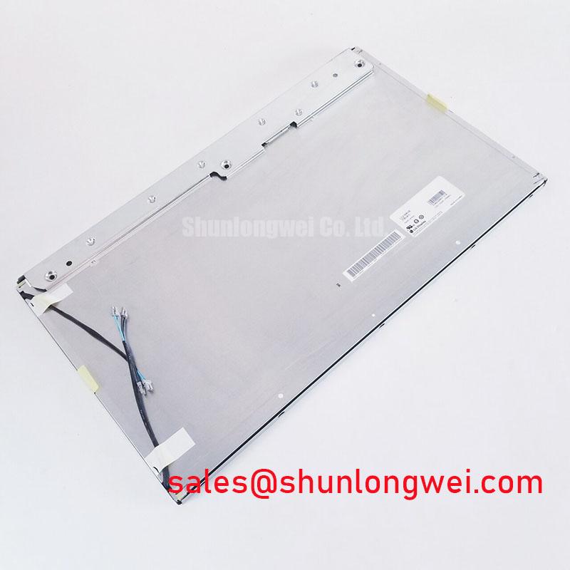
Start incoming inspection by confirming the LM215WF3-SLA2 identification against the original equipment record, then examine the TFT-LCD Display Module under controlled illumination for cracked glass, bezel distortion, damaged flexible connections, and visible contamination.
The LM215WF3-SLA2 is a TFT-LCD Display Module manufactured by LG Display. The available product context does not establish resolution, active-area dimensions, supply voltage, interface pinout, luminance, touch capability, or backlight electrical ratings, so those values should be checked against the original panel documentation before system installation. Industrial suitability must also be confirmed against the requirements of the intended application.
| Manufacturer | LG Display |
| Model | LM215WF3-SLA2 |
| Module type | TFT-LCD Display Module |
Incoming Benchtop Inspection: Driver Bond and Flexible Connection Integrity
Place the panel on an ESD-safe, non-abrasive work surface and inspect the glass edge, bonded driver region, flexible tails, and connector bodies before applying power. A visual inspection should look for edge impact marks, lifted adhesive areas, folded flexible circuits, uneven connector seating, and pressure marks caused by packaging or an unsuitable fixture. These observations do not identify a single failure mechanism by themselves, but they determine whether electrical testing should proceed.
Use a controlled primary-colour sequence with red, green, blue, white, black, and neutral grey test fields. The purpose is to separate isolated pixel behaviour from large-area illumination or signal problems. A bright-field inspection can expose stuck or inactive pixels, while a black field helps reveal light leakage, localized mura, and uneven panel pressure. Repeat the test after the panel reaches a stable operating condition because temperature can influence liquid-crystal response and the apparent severity of grey-level non-uniformity.
A 45-degree flashlight inspection is useful when a dark region appears abnormal. Sweep the light across the front surface without pressing the glass. If the shadow or irregular region changes with the angle of illumination, check the front surface, optical stack, bezel pressure, and backlight path. If the defect remains tied to a particular row or column while the surface remains physically clean, compare the signal path and driver bonding area with a known-good display. This is a diagnostic method, not a substitute for the manufacturer’s panel-level failure criteria.
Where present, COG and TAB bonding areas require non-contact handling. Do not probe exposed bonded regions with metal test leads, and do not use a finger to press the glass in an attempt to restore an intermittent line. When the image shows row, column, or clock-related instability, verify the source timing, connector seating, ground reference, and cable orientation first. The system integrator should confirm whether the replacement panel uses the same interface family, connector position, pin assignment, pixel clock arrangement, and power sequence as the original assembly.
TTL and LVDS should not be treated as interchangeable descriptions. For an LVDS implementation, the transmitter clock, data pairs, return path, and cable routing should be checked against the original system design. Clock jitter and data hold performance must be evaluated across the intended operating temperature window, within the panel’s documented limits, rather than inferred from the model name. An oscilloscope comparison with a known-good signal path can help identify timing instability, impedance discontinuity, or excessive common-mode disturbance. The required voltage levels and timing limits must come from the original panel documentation and host controller specification.
💡 Bench Tip: Discharge the equipment, use ESD protection, and lock each display cable straight and fully flush before applying power.
Preventing Localized Light Guide Plate Compression Warp on Dark Fields
Before mounting the module into an AGV or forklift telematics enclosure, compare the replacement panel’s mechanical envelope, fixing locations, connector clearance, and bezel contact surfaces with the removed unit. The available product context does not provide confirmed external dimensions or mounting-hole tolerances. Those mechanical values should therefore be taken from the original panel drawing or the equipment manufacturer’s service documentation.
Dark-field optical defects can be affected by uneven frame pressure, twisted brackets, cable interference, or a chassis surface that is not planar. A practical inspection uses a black image field while the panel is supported in the intended enclosure. Tighten the fasteners progressively in a cross pattern and observe whether a bright or dark region changes as mechanical loading changes. This helps distinguish enclosure-induced optical stress from a persistent panel or signal-path defect.
Any proposed fastener torque must be treated as a Design Consideration, not as an LM215WF3-SLA2 factory specification. If the equipment drawing specifies M3 hardware and a controlled torque range such as 0.35 to 0.45 N·m, the integrator should verify that value against the chassis material, thread engagement, bracket stiffness, gasket compression, and the panel manufacturer’s mechanical documentation. Do not transfer a torque value from another display without checking the complete mounting stack.
The same discipline applies to claims about light-guide construction, optical films, and backlight lifetime. The available product context identifies this part as a TFT-LCD Display Module, but it does not confirm a particular light-guide material, luminance rating, LED arrangement, or lifetime curve. A statement such as “50,000 hours to 50 percent brightness” would require a supporting factory specification or controlled reliability report. In incoming quality work, record the initial brightness and uniformity method, driver condition, ambient temperature, and instrument settings so that later comparisons remain meaningful.
For a rugged vehicle display, vibration and enclosure shock should be evaluated at the complete assembly level. The panel, carrier, cable, connector lock, protective window, and mounting bracket interact mechanically. An integrator may evaluate this model for automated guided vehicle or forklift display equipment when the electrical interface, mechanical envelope, environmental sealing, and optical requirements are confirmed. The product page for LQ201U1LW31 can also be reviewed as a separate display reference, but compatibility must be established from documented specifications rather than appearance alone.
Solid-State Backlight Driving, PWM Dimming, and Flicker Checks
Do not assume the backlight architecture from the model designation. The available product context does not confirm whether this specific unit requires a particular LED constant-current driver, a CCFL inverter, a defined PWM range, or a specific dimming polarity. The system integrator should verify the required supply voltage, backlight method, enable signal, dimming input, connector pinout, and current limits from the original panel documentation.
When the host equipment uses a constant-current backlight driver, inspect the complete driver loop rather than evaluating the panel in isolation. Confirm current regulation during start-up, normal brightness, minimum brightness, and fault recovery. If PWM dimming is used, observe the enable and dimming waveforms with an oscilloscope and check whether the chosen frequency creates visible flicker, audible noise, camera banding, or interaction with the vehicle controller. A proposed 1000:1 dimming ratio is an application target that requires confirmation from the actual panel and driver combination; it should not be presented as an LM215WF3-SLA2 factory rating without a source.
For differential display links, route the pair as a controlled transmission path with a continuous return reference and minimal stub length. A commonly used 100 ohm differential target may be a useful Design Consideration for LVDS routing, but the final value, tolerance, connector geometry, cable construction, and termination arrangement remain system-dependent. Verify eye opening, clock stability, pair skew, and susceptibility to nearby servo, motor, and switching power wiring under the actual enclosure conditions. A nominal impedance value alone does not prove EMC performance.
Backlight noise can be investigated by separating optical and electrical observations. First check whether the luminance variation follows the PWM command. Then compare it with driver current ripple, supply disturbance, cable movement, and host processor activity. Acoustic buzz can originate in the driver, enclosure, magnetics, or mounting structure, so it should not be assigned to the display module without a controlled isolation test.
The LQ10D321 may be reviewed as a separate display reference. It is not a confirmed substitute, companion, or pin-compatible device for the LM215WF3-SLA2. The original host schematic and panel documentation must govern the final connection.
High-Humidity Storage Margins and Delamination Prevention
Store and handle the module according to the original LG Display documentation, using packaging that prevents condensation, abrasive contact, and mechanical loading on the glass. The available product context does not establish a humidity qualification, thermal-cycle rating, storage duration, perimeter seal construction, or delamination limit. Those environmental values must not be inferred from an intended industrial application alone.
For a proposed 60°C and 90% relative-humidity evaluation, treat the condition as a system-level engineering test rather than an official LM215WF3-SLA2 rating. Define the test fixture, powered or unpowered state, condensation controls, inspection intervals, electrical checks, and acceptance criteria before testing. After exposure, inspect the bezel edge, flexible connections, display uniformity, connector surfaces, and host-side power sequence. Any observed haze, bubble, colour shift, line defect, or intermittent operation should be documented with images and correlated with temperature and humidity history.
Sub-zero operation can change liquid-crystal response behaviour and increase visible grey-to-grey lag. The correct evaluation should use moving test patterns and several grey transitions rather than a single static image. Verify whether the observed response is caused by panel temperature, source timing, frame-rate conversion, image processing, or the display interface. A claimed operating range such as minus 30°C to plus 85°C requires an applicable factory environmental specification; it should not be assigned to this model solely because the target equipment is industrial.
Anti-glare, anti-reflection, high-brightness, glove operation, and wet-touch performance also require confirmation at the complete HMI level. The supplied information does not verify a touch sensor, AG or AR surface treatment, optical bonding method, luminance value, or water-rejection performance for this model. If the LM215WF3-SLA2 is placed behind a protective window in an AGV or forklift display, test readability under direct light, viewing angle, surface moisture, and enclosure reflections. If touch input is included, test glove operation and wet-touch performance separately from the LCD image path, along with the touch controller and cover window.
For broader enclosure, sealing, optical, and interface planning, consult the Industrial Display & HMI Solutions engineering guide. It provides system-level context, while the original panel documentation remains the controlling source for this model’s electrical and environmental limits.