

Content last revised on September 10, 2026
Thermal Expansion Clearance Sizing across Heavy Industrial Metal Enclosure Cutouts
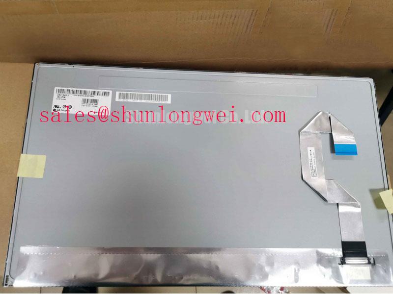
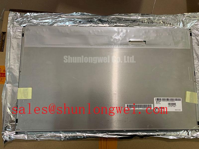
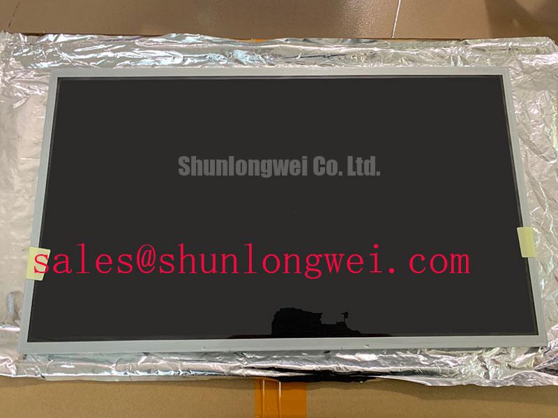
Begin incoming inspection of the LM215WF3-SDA1 by checking the TFT LCD display module’s bezel, visible polarizer surface, connector area, and rear enclosure under diffuse light before it is connected to a controller. This LG Display unit is identified as an Industrial Grade LCD/HMI Panel in a TFT LCD Display Module enclosure, with its factory specification status recorded as verified. The replacement decision should still be based on the original equipment documentation, including mechanical drawing, connector assignment, supply requirements, display timing, and backlight interface requirements.
For repair intake, keep the removed panel and its mating cable together until pinout and mechanical compatibility are confirmed. A display that physically fits a cabinet cutout can still be unsuitable if the interface, power sequencing, or mounting datum differs from the original assembly. Where a same size or resolution class panel is under consideration during material evaluation, LQ201U1LW31 can be reviewed against the host equipment documentation as a separate compatibility exercise rather than treated as a direct substitution.
Place the LM215WF3-SDA1 into the equipment enclosure without fastening it first, then inspect the perimeter clearance from the front viewing area and rear housing. This simple dry fit reveals whether a formed metal cutout, gasket ridge, mounting stud, or front retaining frame contacts the panel at a single point. Localized force is a common installation concern because an otherwise clean display can show nonuniform dark-field shading after the bezel is tightened.
The product identification provided for this panel confirms its industrial LCD/HMI classification and TFT LCD module construction, but it does not establish a published chassis envelope, mounting-hole pattern, bezel depth, or specified fastener torque. The system integrator should obtain these values from the original panel documentation before releasing a replacement assembly. Do not infer dimensions from a nominal screen class or from the opening in an old cabinet.
As a Design Consideration, installers commonly use a cross-pattern tightening sequence for small M3 display retainers so clamping load is distributed rather than concentrated at one edge. A torque range of 0.35 to 0.45 N·m is a general industry starting reference for some M3 fastening arrangements, not an LG Display factory rating for this model. The correct torque depends on the screw, thread engagement, bracket stiffness, retaining frame, gasket compression, and mechanical drawing of the installed assembly.
Allow the metal enclosure, front overlay, and display mounting structure to move with their respective thermal expansion characteristics. The practical objective is to retain the panel securely while avoiding a rigid condition that transfers enclosure stress into the visible area. After final tightening, inspect a black image, a white image, and a low-gray image at normal viewing distance. Edge brightening, pressure shadows, or changes that appear only after fastening should be documented before the unit is returned to service.
⚡ Safety Interlock Note: Disconnect panel and backlight power before releasing or inserting the display cable, and close the connector lock only when the flex cable is fully level and seated.
Direct sunlight performance should not be assumed from the product category alone. Requirements such as contrast stability above 500:1 at 50,000 lux, anti-glare surface treatment, and outdoor readability require confirmation from the applicable factory optical specification. For equipment such as a marine radar or navigation bridge console, the enclosure designer should assess the actual viewing position, window exposure, moisture sealing, thermal loading, and display hood geometry rather than relying on an unverified brightness or contrast claim.
Polarizer Durability & Optical Retardation Film Inspection under Direct Industrial Lighting
With the panel supported on a clean, nonabrasive fixture, illuminate the screen uniformly and inspect the front surface from several normal operating positions. Look for scratches, pressure marks, localized haze, residue from old overlays, and uneven reflections that become obvious under oblique industrial lighting. Record findings with the screen powered only after the visual inspection is complete, because power-on images can hide fine surface defects that are apparent on an unlit panel.
No factory viewing-angle specification, panel mode, anti-glare construction, or polarizer material detail has been supplied for the LM215WF3-SDA1. It would therefore be inaccurate to label it TN, IPS, or MVA, or to claim a symmetric 85°/85°/85°/85° viewing cone. Those values can be relevant comparison criteria during equipment refurbishment, but they are not confirmed specifications for this display module.
For a control room display or an exposed bridge-console position, evaluate image polarity, grayscale consistency, and reflected-light behavior using the real controller and the expected operator sightlines. A panel can appear acceptable on a workbench and become difficult to read when a dark user interface is viewed through reflected daylight. The inspection should include solid black, white, red, green, blue, and multiple gray patterns, followed by a visual review at the intended mounting angle.
Cold ambient operation also needs a controlled assessment. Liquid-crystal response can slow as temperature falls, but no operating temperature range or gray-to-gray response specification has been provided for this model. Do not state that the LM215WF3-SDA1 is rated for −20°C to −30°C, and do not add a heater strip solely from a generic display practice. When cold starts are part of the host equipment duty cycle, the system designer should verify the original panel’s approved temperature range, controller timing behavior, condensation controls, and any existing thermal-management arrangement.
Clean only with a method approved for the equipment’s front assembly. Aggressive solvents, rough wipes, or contaminated cloths can alter the apparent surface condition and make later optical fault isolation difficult. If a protective window is used ahead of the LCD, test the complete stack for reflections and image clarity rather than judging the bare panel in isolation.
Backlight Driving, Dimming & Flicker Suppression
Before applying power, trace the host cable from the panel connector to the controller board and identify the display signal path separately from the backlight supply path. The supplied product information identifies a TFT LCD module but does not confirm the backlight technology, driver voltage, current rating, dimming method, enable logic, or connector pin allocation. The system integrator should verify the required supply voltage and backlight interface from the original panel documentation and the host controller schematic.
This distinction matters during repair because a blank image can originate in several places: panel input power, source timing, cable retention, controller initialization, backlight enable control, or a driver protection response. Avoid assigning a single cause from appearance alone. Compare supply rails and control waveforms with a known-good signal path where available, using suitable probing practices that do not disturb fine-pitch display connectors.
Constant-current WLED driving, 1000:1 PWM dimming, and flicker behavior are not confirmed factory specifications for the LM215WF3-SDA1. Likewise, the figures sometimes associated with CCFL ignition, PWM frequency, or a 50,000 hour backlight half-life must not be applied to this model without the relevant manufacturer documentation. A converter intended for one lamp or LED arrangement must never be connected to an unverified replacement panel on the assumption that the connector shape is sufficient evidence of compatibility.
As an Engineering Recommendation, evaluate dimming with the complete host display chain at the brightness settings actually used by operators. Check for visible modulation, camera-band artifacts where machine vision or recording is involved, and audible noise from the host driver assembly. The duty conditions, controller architecture, cable routing, and driver design determine acceptable results. Where the original system includes backlight-open, short-circuit, or overvoltage protection reporting, confirm how that reporting behaves before declaring the panel itself defective.
During bench work, inspect the flex cable’s contact edge for uneven insertion marks and confirm that the locking feature holds the cable evenly across its width. A cable that is slightly skewed can create intermittent image loss, unstable colors, or startup-dependent behavior. Do not repeatedly flex the cable to chase a fault; secure it in the intended service position and perform controlled observation while the equipment remains safely supported.
Thermal Cycling Degradation of Polarizer Adhesives & Sealant Gasket Integrity
Thermal-cycle screening begins with the installed assembly, not with an assumed environmental rating. Check that the panel perimeter is not pinched by a swollen gasket, a distorted front frame, or deposits left from previous sealing materials. Review the cabinet’s drain paths, pressure equalization approach, cable strain relief, and front-window condition because these external features influence the display environment even though they are not part of the LM215WF3-SDA1 itself.
The provided factory information does not publish a thermal-cycle range of −30°C to +85°C, adhesive performance, perimeter sealant construction, or liquid-crystal response time for this exact model. These figures should therefore be treated as system test conditions only when mandated by the equipment specification, not as product ratings. Engineers evaluating a display for a high-salt or outdoor-facing enclosure should validate the complete enclosure assembly for ingress control and optical stability under its own documented environmental plan.
When a screen shows delayed gray transitions during cold starts, inspect conditions methodically. Confirm the actual panel temperature, controller output stability, cable seating, and whether the symptom changes as the enclosure reaches its normal operating state. Slow optical transitions may be temperature related, but unstable data transfer, controller timing, supply variation, or mechanical cable stress can produce superficially similar behavior. Capture the display signal at the known-good controller location and again at the panel connection when the interface documentation permits a safe measurement.
The LM215WF3-SDA1 interface standard, transmitter clock tolerance, data hold requirement, and power-up sequence have not been provided in the available official factory information. It is not appropriate to claim TTL or LVDS operation for this model without confirmation. The replacement process should preserve the original signal type and sequence, then verify timing margins with the host system documentation and switching tests across the relevant equipment temperature window.
For technicians building a repeatable inspection record, retain photographs of the unpowered surface, connector seating, mounting clearances, and powered full-screen test images. Add notes on any image change after enclosure fastening or temperature stabilization. For broader test planning around optical evaluation, mechanical integration, and interface verification, consult The Ultimate Guide to Industrial TFT LCD Technology alongside the original equipment service documents.