Content last revised on September 22, 2026
Product Identification and Incoming Inspection
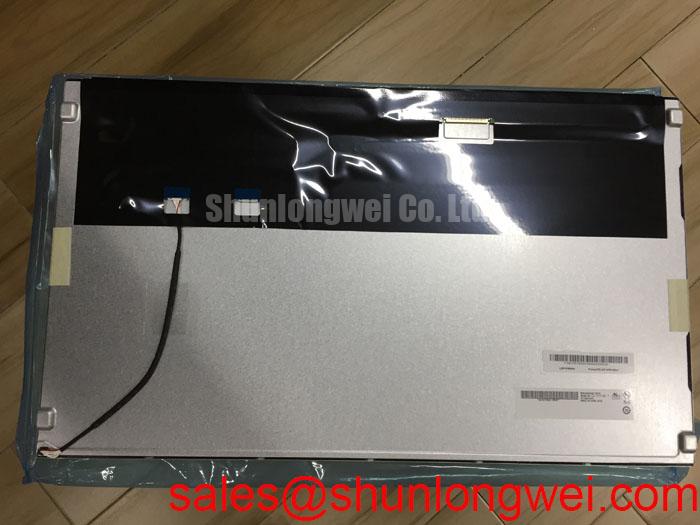
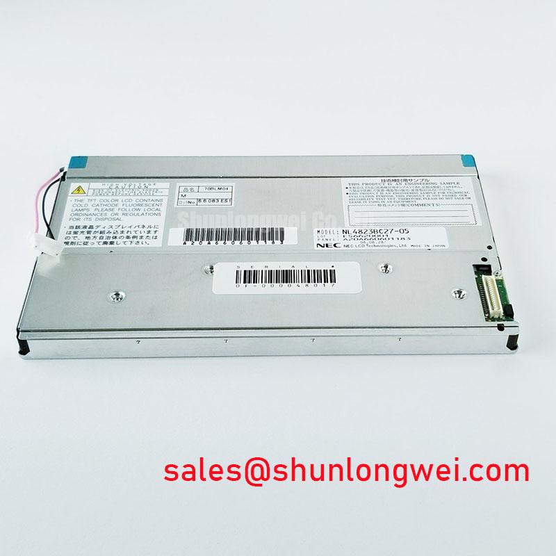
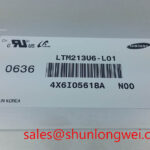
Begin incoming inspection of the LTM213U6-L01 by checking the TFT-LCD module label, connector condition, glass surface, frame, and visible contamination under controlled lighting before applying power. The available factory information identifies this unit as an Industrial Grade LCD/HMI Panel manufactured by Samsung, with a TFT-LCD Display Module construction. Supply voltage, resolution, interface mapping, backlight type, viewing angle, dimensions, and timing values should be confirmed against the original panel documentation before installation.
| Parameter | Verified Information |
|---|---|
| Model | LTM213U6-L01 |
| Manufacturer | Samsung |
| Product category | Industrial Grade LCD/HMI Panel |
| Module construction | TFT-LCD Display Module |
| Specification status | Key specifications require confirmation from the original factory documentation |
| Application role | Industrial HMI and equipment monitoring display, subject to system verification |
Logic Supply Voltage Sequencing and Interface Verification
Before connecting the panel to a controller, identify the original supply rails and signal interface from the equipment service documentation. The available factory data for the LTM213U6-L01 does not confirm whether the host system uses a 3.3 V or 5.0 V logic supply, so the system integrator should verify the required supply voltage from the original panel documentation rather than applying a guessed rail.
Power sequencing is a design consideration rather than a confirmed model specification. Engineers should observe the rise of the logic supply, display enable signal, and video clock with an oscilloscope while comparing the waveform to a known good assembly. An abnormal startup sequence may contribute to incomplete initialization, unstable images, or driver stress, but the measured signal path should be checked before assigning a single cause.
For LVDS installations, verify the cable type, pair continuity, connector orientation, termination arrangement, and differential routing used by the host board. The suggested 100 ohm differential impedance often appears in LVDS system design, but it is not an official electrical rating confirmed here for this model. JEIDA and VESA data mapping should also be checked against the controller configuration. Incorrect mapping can produce color order errors, split images, or misplaced image data.
Cold-start evaluation deserves separate attention when the panel is considered for an equipment cabin or telematics display. Response time can change with ambient temperature, while a heater or enclosure temperature-control system can alter startup behavior. Any heater strip, thermal controller, or delayed enable circuit must be validated as part of the complete display assembly. The related LQ10D321 may be reviewed as a neutral reference for a coordinated display power topology, but compatibility must be established from the actual circuit documentation.
Mechanical Handling and Pixel Defect Screening
Inspect the glass edge, mounting points, bezel, flex connection, and connector locking features before functional testing. A panel can show intermittent lines or missing image regions when the cable is not seated evenly, but these observations require controlled reseating and comparison testing before a glass or driver fault is identified.
Use a three-stage primary-color inspection with red, green, and blue test fields, followed by black and white screens. This process helps separate visible pixel defects from illumination nonuniformity. A 45-degree flashlight inspection can reveal shadows, surface marks, pressure points, or areas where reflected light changes around the bezel. It should be used as an observation aid, not as proof of a particular internal failure mechanism.
Pixel screening should be performed after the display reaches a stable operating condition. Record the test pattern, viewing distance, ambient illumination, and observed location of any abnormal pixel. The available factory information does not define an acceptable pixel defect class for this model, so procurement or repair acceptance should follow the equipment manufacturer’s criteria.
Signal integrity should be checked at the connector and, where accessible, at the transmitter side of the cable. Clock jitter, data hold behavior, grounding, and shield continuity can vary across the industrial temperature range. If a line defect changes when the cable is moved, stop mechanical manipulation and inspect the connector retention and cable strain path. Do not press directly on the glass or flex area.
Bench Tip: Disconnect power before inserting or removing the display cable, protect the work surface against ESD, and close the connector lock only after the cable is fully aligned and parallel with the socket.
Viewing Direction, Grayscale Assessment, and Surface Readability
Do not assume that the LTM213U6-L01 uses a particular liquid-crystal mode, viewing cone, or surface treatment without the original optical specification. The supplied factory information confirms the TFT-LCD category but does not verify normally white TN operation, IPS or MVA behavior, a symmetrical 85 degree viewing angle, or a specific anti-glare etch.
During incoming QA, evaluate text and grayscale bars from the intended operator position first, then inspect vertical and horizontal viewing changes. Look for grayscale inversion, loss of dark detail, color shift, and reflected cabin lighting. These observations are especially relevant when the panel is evaluated for a heavy mining shovel or earthmoving equipment telematics display, where the final enclosure angle and ambient light can differ from a bench setup.
Backlight control must be checked at the system level. The panel documentation should confirm whether the installed assembly uses LED drive, another illumination arrangement, PWM dimming, or analog control. Do not substitute a presumed PWM range of 200 Hz to 1 kHz or a presumed duty-cycle relationship for the manufacturer’s electrical data. Verify the driver output, brightness command, visible flicker, and acoustic behavior with the actual controller.
For optical benchmarking, the LQ201U1LW31 can serve as a neutral same-class reference during a compatibility review. It should not be treated as a drop-in replacement unless connector position, active area, interface timing, mounting geometry, optical properties, and controller support have all been confirmed.
Cold-Start Response and Industrial Integration Checks
Cold-start testing should compare the first image, image stability, visible response lag, and brightness behavior at the temperatures permitted by the original equipment specification. The available information does not establish a guaranteed operating range, gray-to-gray value, perimeter seal construction, or backlight lifetime for this model. Those values must be obtained from the applicable factory datasheet or equipment service record.
Liquid-crystal response can vary with temperature, and a slower transition during a cold start does not by itself identify a failed panel. Compare the same test pattern at controlled conditions, verify supply stability, inspect the video clock and enable signals, and check whether the host controller is applying the expected initialization sequence. Any enclosure heater or airflow arrangement should be validated for uniform panel warming rather than judged from one local temperature measurement.
Backlight brightness maintenance should be assessed with the installed backlight driver and the specified thermal environment. A claimed 50,000-hour life or 50 percent brightness point should not be assigned to this model without a source in the relevant factory specification. Similarly, enclosure sealing and thermal cycling should be reviewed as system design considerations, not treated as confirmed module qualifications.
For harsh-environment maintenance planning, the Industrial Display & HMI Solutions reference provides a broader engineering context. High-voltage insulation references such as Polyimide Film High Voltage Dielectric Insulation and Partial Discharge Detection concern power assemblies and insulation systems, not confirmed internal construction or certification of the LTM213U6-L01. They should therefore remain external design references when the display is installed beside high-energy equipment.