

Content last revised on September 23, 2026
Surface Anti Glare (AG) & Anti Reflective (AR) Etched Coating for High Ambient Readability
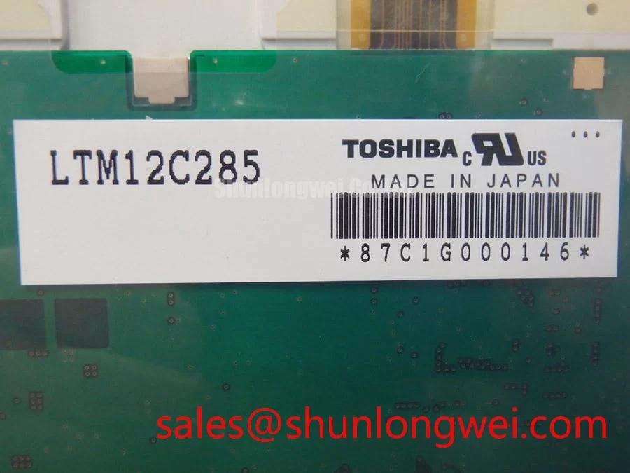
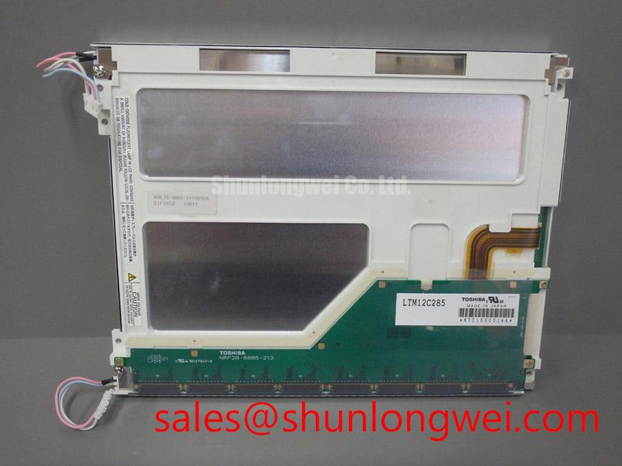
Before assessing daylight readability, examine the active viewing surface under an oblique inspection light. A matte appearance can result from an anti glare treatment, a front overlay, a touch assembly, or wear on the outer protective layer. The verified product classification for LTM12C285 confirms a TFT LCD display module, but it does not establish an official anti glare coating type, anti reflective treatment, viewing cone, contrast ratio, or brightness value. Those details must be confirmed from the original panel record or the equipment maker’s service documentation.
TN displays can show tone or grayscale changes as the viewing direction moves away from the intended axis, while IPS and MVA technologies are often evaluated for more symmetric viewing behavior. It would be incorrect to assign any of these panel modes to LTM12C285 without an approved specification. During a practical review, compare the replacement candidate and removed panel at the actual operator angle, with the same cover window and enclosure geometry. This exposes whether reflections, surface haze, or apparent grayscale inversion are caused by the display assembly or by the machine front glass.
LED backlight lifetime curves and half brightness figures also require model specific factory evidence. No field life figure should be inferred from a generic constant current driver arrangement. 💡 Pro Tip: Compare the display through the final cover lens rather than on an open bench, because the enclosure window can dominate perceived reflection and contrast.
Suppressing Pixel Jitter & Horizontal White Lines Induced by Adjacent 400V Motor Drives
When a machine panel is installed near a nominal 400 V variable frequency drive, inspect the image while the drive is inactive, accelerating, decelerating, and holding speed. Pixel jitter, intermittent horizontal bands, or pale line artifacts can be related to conducted interference, radiated coupling, loose shield termination, unstable display supply rails, connector contact issues, or an unrelated controller timing fault. The observed symptom alone does not identify one cause.
Design Consideration: route the display signal assembly separately from high energy motor conductors where the enclosure allows, maintain the intended shield termination path, and avoid pigtail like shield connections that reduce high frequency effectiveness. A 360 degree shield termination at the enclosure entry is commonly evaluated where the cable and connector system support it. Common mode ferrite treatment may also be assessed at the affected cable boundary, but its material, placement, and effectiveness must be verified against the actual noise spectrum and signal integrity of the host equipment.
The LTM12C285 factory information provided here does not establish LVDS, TTL, connector pinout, data polarity, or JEIDA and VESA mapping. The system integrator should verify the required interface from the original panel documentation before applying probes or substitution hardware. Use an oscilloscope comparison against a known good signal path when possible, checking whether the disturbance correlates with motor switching events and whether the panel supply remains stable at the display connector.
For terminology and broader inspection methods used when evaluating industrial display installations, consult The Ultimate Guide to Industrial TFT LCD Technology. Industry test and documentation practices can also be cross checked with JEDEC Solid State Technology Association Standards where an applicable component or system standard is identified.
Suppressing Acoustic Capacitor Buzz & EMI Emissions across 200 Hz to 1 kHz PWM Frequencies
Do not assume that LTM12C285 uses either a CCFL or LED backlight, because the supplied verified product information does not define the backlight technology. This distinction matters during repair because a high voltage lamp inverter, an LED constant current driver, and the associated dimming control can produce different audible and electrical behaviors. The system integrator should verify the required backlight supply, enable control, dimming method, and connector assignment from the original panel documentation.
Audible noise around PWM dimming operation may originate in inductive parts, ceramic capacitors, the power converter enclosure, or mechanical resonance in nearby assemblies. It should be investigated with the panel installed in its intended mounting condition, since a loose bracket or front bezel can amplify vibration that is not intrinsic to the display module. If a noise condition accompanies visible instability, test the backlight driver input and control signals separately from the video path before changing parts.
Design Consideration: evaluate dimming behavior across the actual command range used by the CNC operator panel or teach pendant, then observe the image for flicker, brightness discontinuity, and interference during motor activity. Claims regarding PWM ratio, cold ignition voltage, contrast under sunlight, electromagnetic compliance, or backlight operating life require the original factory specification or system level test evidence. A display module by itself should not be represented as independently compliant with complete equipment EMC requirements.
Thermal Cycling Degradation of Polarizer Adhesives & Sealant Gasket Integrity
Examine the perimeter of the removed display and its enclosure gasket for compression set, contamination, edge lifting, or uneven clamping marks. Temperature cycling can alter the behavior of liquid crystal materials, optical films, seals, cable assemblies, and the enclosure itself, yet no operating temperature range, response time, polarizer construction, or gasket material is established for LTM12C285 in the verified information supplied here. Any stated thermal limit must therefore come from the original factory record rather than from a generic industrial display assumption.
At low temperature, a slower image transition can be observed in some LCD technologies. At elevated temperature, an enclosure may alter optical appearance or stress the mounting stack. These observations should be assessed as service conditions, not used to declare an internal defect without comparison to known good equipment and applicable documentation. When evaluating a replacement for industrial automation CNC operator panels or robot teach pendants, verify the complete mechanical stack, including front lens clearance, mounting points, connector strain relief, and the permitted enclosure opening tolerance.
Signal pair impedance and timing skew are host board and cable assembly characteristics, not verified LTM12C285 factory ratings. Engineering Recommendation: preserve the original differential routing strategy where a differential interface is documented, minimize avoidable discontinuities, and validate image stability with the final cable length and nearby electrical loads present. Practical warning: Disconnect power and allow stored energy in the host equipment to discharge before connecting or removing any display cable.