

Content last revised on October 13, 2026
Preventing Spurious Faults: Diagnosing Gate-Emitter Insulation Issues for CP15TD1-24A
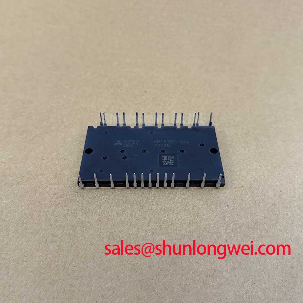
Check the module marking against the drive schematic before testing. Model: CP15TD1-24A | Manufacturer: Mitsubishi Electric | Specified voltage rating: 1200 V | Current class: 15 A | Package: Mitsubishi IGBT Module | Pinout and rating conditions: Consult the datasheet.
I start cold screening with the DC link discharged and the module electrically isolated from paths that could distort the meter reading. For the CP15TD1-24A, identify the main terminals from the terminal drawing rather than their physical position. Use diode-check mode across the schematic-defined diode paths, recording the response in both polarities. Compare equivalent paths under the same meter conditions; a difference warrants investigation, not an automatic failure verdict.
Field Alert: Verify that the DC link is discharged before disconnecting terminals or attaching test leads.
Design Consideration: A handheld meter can reveal gross shorts or unexpected conduction, but it cannot establish gate dielectric integrity or switching performance under operating voltage. Where the documented interface exposes the gate and emitter directly, isolate the driver before checking their resistance. Driver circuitry and protection components can otherwise dominate the reading. Avoid applying insulation-test voltage to control terminals unless the manufacturer explicitly permits that procedure.
Examine terminal supports, contamination tracks and displaced insulating barriers alongside the electrical measurements. Preserve the equipment’s specified creepage and clearance when reconnecting conductors; cable placement must not bridge an insulating gap. The Mitsubishi Electric semiconductor resource is the manufacturer reference point for device documentation. For measurement traceability, the National Institute of Standards and Technology provides metrology resources, not acceptance thresholds for this module.
Preventing Spurious Faults: Overvoltage Trip Prevention for CP15TD1-24A
Trace the braking circuit before attributing a deceleration overvoltage trip to the power module. Determine from the equipment schematic whether a braking switch and resistor are present, how they connect to the DC link, and which controller enables them. The 1200.0 V module rating is an electrical boundary, not a brake activation threshold or a prescribed operating bus voltage.
Design Consideration: Assess braking capacity against the load’s returned mechanical energy, deceleration profile and repetition rate. The system engineer should establish resistor pulse-energy capability, thermal recovery and braking-switch stress from the equipment duty cycle. Check resistor continuity, connections and thermal protection before a controlled operational test. An open braking path, an incorrect command or insufficient energy-handling capacity can produce similar symptoms; distinguish them through measurements rather than replacing the module on the fault code alone.
Follow the terminal drawing when reconnecting the DC bus and braking branch. Inspect busbar seating, fastener retention and insulating supports for movement or distortion. Tightening should follow the applicable assembly specification, with no improvised torque value. Maintain the original separation between power conductors and control wiring, and check that protective covers retain their intended position after fastening.
For compatibility assessment, light industrial automation drives and multi-joint robotic actuator drives are possible equipment contexts, subject to their electrical and mechanical requirements. The CM200DU-24H offers a separate comparison reference, not an established substitute. Compare topology, terminal mapping, control interface, mounting geometry and thermal requirements before considering any different module.
Assembly Integrity & Layout Architecture: Implementing Oscilloscope Waveform Verification for CP15TD1-24A
Capture the existing drive’s switching waveforms before changing external gate resistance. First establish whether its documented control interface permits separate turn-on and turn-off resistance adjustment. A legacy board’s existing resistor values should not be transferred automatically to a different power module, and the 15 A current class alone provides no basis for selecting them.
Engineering Recommendation: Use suitably rated differential probes and a controlled commissioning procedure to compare gate behavior, switching-node transitions and current. Keep the measurement loop compact so probe pickup is not mistaken for device ringing. Observe turn-off voltage peaks together with the DC-link voltage, then assess them against the device’s documented limits. If the gate interface is not externally accessible, investigate the permitted control and power measurement points rather than treating control inputs as discrete gates.
Design Consideration: Where resistor adjustment is supported, evaluate turn-on and turn-off changes separately. Slower transitions can reduce ringing but increase switching loss; faster transitions can increase overshoot and disturbance of adjacent signals. Final values belong to the validated drive design, supported by waveform and thermal measurements. The IGBT Design & Integration reference covers the interaction between gate drive, thermal management and circuit topology.
Inspect the commutation path before attempting to suppress every oscillation through resistance changes. Minimize unnecessary conductor loop area within the approved assembly, preserve insulation spacing and verify busbar contact seating. Repeat the measurements after reassembly under the intended operating conditions, recording probe locations and test settings so subsequent comparisons remain meaningful.