
Content last revised on October 13, 2026
Preventing Spurious Faults: Short-Circuit Energy Let-Through Matching Guidelines for CM200DU-24H
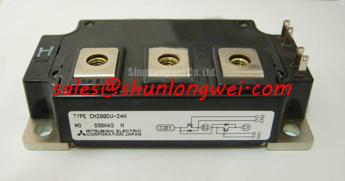
With the DC link discharged and the module disconnected from its gate driver, check the terminal markings against the equipment schematic before taking diode-mode readings on the CM200DU-24H. Keep the gate referenced to its corresponding emitter during static checks, and compare both switch positions using the same meter polarity and temperature. A diode-mode reading can help identify an abnormal conduction path, but it does not establish blocking capability or switching performance.
The Mitsubishi Electric CM200DU-24H IGBT module has specification ratings of 1200 V collector-emitter voltage, 200 A DC collector current under the datasheet rating conditions, and ±20 V gate-emitter voltage. Its listed collector-emitter saturation-voltage value is 2.4 V at a junction temperature of 25°C; consult the applicable manufacturer datasheet for the test current, gate voltage, and whether this value is typical or limiting. The isolation-voltage specification is 2500 Vrms, and the listed junction-to-case thermal resistance is 0.11 K/W. Current-rating conditions, thermal-resistance limits, isolation-test duration, dynamic limits, and mechanical details require the applicable manufacturer datasheet.
💡 Bench Tip: Use ESD protection and compare cold-state readings with a known-good reference only after verifying that the DC link is discharged.
Compare the semiconductor fuse’s total-clearing I²t at the actual circuit voltage and prospective fault current with the equipment’s protection-coordination requirements. As a Design Consideration, fuse let-through and IGBT short-circuit withstand describe different stresses: a fuse limits fault energy in the power circuit, while gate-driver protection must respond to semiconductor overcurrent within the device’s permitted operating conditions. The 200 A rating is not a short-circuit withstand specification.
Trace the fault-current path through the DC-link capacitor, busbars, module, and protective device. Check the fuse’s DC interrupting capability and the influence of circuit inductance on clearing behavior. Coordination should address both rapid gate shutdown and interruption of a sustained fault; selecting a fuse from nominal current alone cannot establish protection against module enclosure damage.
For unexplained protection trips, examine the recorded gate-drive fault, current-sensor output, and DC-link behavior together. An unexpected trip may involve sensing interference, switching transients, or a genuine overload. As an Engineering Recommendation, preserve conductor clearances according to the equipment’s insulation requirements and keep sensing connections away from high-current switching loops. Change the protection settings only after identifying which signal initiated shutdown.
Transient Dynamics & Electrical Design: Dynamic Power Loss Dissipation and Multi-RC Modeling on CM200DU-24H
Use the actual overload pulse duration and loss waveform to evaluate junction heating rather than applying steady-state thermal resistance to every transient. The listed 0.11 K/W junction-to-case value describes a thermal-resistance characteristic; it does not supply the time constants needed for a multi-RC transient model.
An Engineering Calculation should use manufacturer transient thermal impedance or validated thermal-model coefficients to combine pulse losses with the preceding thermal history and measured case temperature. This separates a short pulse from repeated loading that accumulates heat. Switching loss, conduction loss, and cooling conditions all affect the resulting peak junction temperature; a case-temperature reading alone does not capture the instantaneous junction excursion.
As a Design Consideration, reduce commutation-loop area and keep the outgoing and return busbar paths closely coupled to suppress inductive turn-off overshoot. Where a snubber is required, its connection path should avoid adding unnecessary loop inductance. Component values and layout acceptance limits should follow measured switching behavior, including diode recovery and collector-emitter peak voltage, rather than an assumed universal inductance target.
When comparing the CM200DY-12H, treat it as a separate evaluation candidate, not an established interchangeable replacement. The following comparison identifies the CM200DU-24H boundaries that a replacement review must resolve.
| Comparison point | CM200DU-24H specification | CM200DY-12H evaluation |
|---|---|---|
| Collector-emitter voltage | 1200 V | Consult datasheet |
| DC collector current | 200 A under the datasheet rating conditions | Consult datasheet and rating conditions |
| Gate-emitter voltage | ±20 V | Compare gate limits and driver requirements |
| Thermal and mechanical compatibility | 0.11 K/W listed junction-to-case thermal resistance; verify limits and mounting details in the datasheet | Compare thermal data, terminal layout, and mounting drawing |
Field Diagnostics & Commissioning: Galvanic Gate Drive Isolation in CM200DU-24H Topologies
Separate the module’s 2500 Vrms isolation-voltage specification from the gate driver’s isolation classification when reviewing the schematic. That module rating does not independently establish reinforced isolation for the assembled equipment. As a Design Consideration, driver barriers, isolated power supplies, PCB clearances, and accessible conductive parts require assessment against the applicable equipment safety requirements.
Investigate suspected spurious triggering by measuring gate-emitter voltage at the module terminals with appropriately rated differential instrumentation. Compare gate disturbances with collector-emitter transitions and driver fault timing. Common-mode transient immunity belongs to the driver’s documented performance; acceptance should reflect the measured switching environment, not an assumed module-level immunity rating.
Mitsubishi Electric’s CSTBT technology and motion-control guidance and NX-Series IGBT module information provide manufacturer context, without establishing those technologies or specifications for this model. For resonant switching investigations, Resonant Topologies in Home Appliances explains topology-dependent commutation behavior rather than CM200DU-24H application approval.
When evaluating this module for electric material-handling or forklift low-voltage traction equipment, designers should compare driver compatibility, switching losses, terminal geometry, and cooling interfaces with the original assembly. Complete commissioning by checking both gate channels under controlled operation and recording their waveforms against the equipment’s established acceptance criteria.