
Content last revised on September 26, 2026
CM200DU-24F Thermal-Electrical Optimization: Dynamic Gate Impedance Control for Robust Practical Tuning
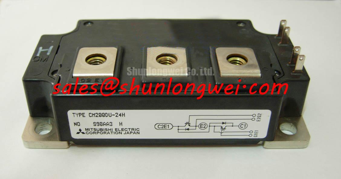
With the DC link isolated and discharged, compare the cold terminal measurements of the CM200DU-24F against the equipment schematic before connecting a gate driver. Mitsubishi Electric identifies this part as a 1200 V, 200 A IGBT module (Official Specification). Those ratings establish the first procurement check; they do not establish that its terminals, mounting arrangement, switching behavior, or protection settings match an installed unit. Record the module marking, map the accessible terminals to the original documentation, and keep the test instrument within its intended measurement range.
A diode-mode check can provide a useful incoming baseline before powered testing. With the module disconnected, measure each accessible antiparallel current path in both probe directions and record the readings alongside a documented, known-good unit tested with the same meter. A reading that differs warrants further investigation; it does not, by itself, identify a failed chip. Gate-to-emitter resistance checks can also flag an unexpected short, provided the technician follows the terminal identification in the original module documentation rather than assuming that similarly positioned terminals have identical functions.
💡 Bench Tip: Keep the gate terminals under appropriate ESD control and compare cold diode-mode readings only with the same meter and probe orientation.
The 1200 V blocking rating and 200 A current rating are Official Specifications, not instructions for selecting a DC-link voltage or continuous equipment load. As a Design Consideration, the gate-driver review should start with the installed schematic: trace the turn-on and turn-off paths, gate return, driver supply, and any clamp path. A rising collector voltage can couple into an off-state gate. If that coupling produces unwanted turn-on, the engineer can evaluate gate-loop impedance, an active Miller clamp, or negative off-state bias, then verify the selected arrangement against the driver and module documentation during switching tests. No off-state bias value can be assigned from the ratings above alone.
Keep the gate and return paths compact to limit parasitic inductance that can contribute to ringing. Where the PCB separates power and driver circuits, check the actual creepage, clearance, and isolation requirements against the equipment design rather than treating the module voltage rating as a layout rule. Probe the gate at the relevant module terminals during controlled switching: a clean driver-output trace does not necessarily show the voltage present at the gate after lead and connection effects. For source identification and additional manufacturer documentation, see Mitsubishi Electric Power Semiconductors & High-Power Modules.
For an equipment repair comparison, CM100DY-12E can be reviewed as a separate module reference, not a presumed substitute. Confirm each candidate’s official voltage and current ratings, terminal diagram, footprint, thermal limits, and switching requirements before making a compatibility decision. The CM200DU-24F rating pair alone cannot establish interchangeable gate-drive or mechanical behavior.
Benchtop Waveform Tuning: Mitigating Stress via Short-Circuit and Overcurrent Protection for CM200DU-24F
Before enabling the power stage, examine how the installed controller prevents simultaneous conduction. Check the commanded gate signals at the driver inputs and then at the module connections; the interval between opposing commands can differ from the effective interval at the devices because propagation and switching delays are not necessarily equal. Dead time is a system setting. It should be validated across the operating conditions of the equipment, with attention to both shoot-through risk and the effects of excessive delay on the output waveform.
Short-circuit response needs a separate verification path. Follow the sensed current or desaturation signal through detection, blanking, fault latching, and gate shutdown on the actual driver board. Type-I and type-II fault descriptions can help organize test cases, but neither a universal detection deadline nor a short-circuit withstand time should be assigned to this module without its applicable manufacturer data. If the driver uses staged or soft turn-off, inspect the collector-voltage response while validating the protection circuit under a controlled, equipment-approved test procedure. Slowing fault turn-off can reduce inductive overshoot, but the resulting current and energy stress must also remain within documented device limits.
For waveform assessment, use measurement methods appropriate to the DC-link potential and compare collector-voltage peaks with the module’s 1200 V Official Specification. A peak near a limit calls for investigation of the bus voltage, commutation loop, gate behavior, and measurement setup; changing a single gate resistor without examining those paths may obscure the cause. Compare repetitive switching traces with fault-event traces rather than treating them as the same operating condition.
In an industrial inverter welder or medium-frequency induction heating supply, phase-angle control and line-frequency ripple belong to the surrounding converter, not to the IGBT module’s factory specification. When such equipment is being evaluated, inspect the rectified bus waveform before attributing current variation to the module. A DC-link MOV and an RC snubber may serve different overvoltage-management roles: their suitability depends on the disturbance, placement, and energy involved. Designers should select and test them against the equipment schematic and measured transients, not assume either network compensates for an unsuitable switching layout. For a related power-stage reference, CM50DY-28H can be examined on its own documented merits; its name does not establish it as a rectifier or as a drop-in part for this position.
At the edge of a converter’s operating range, topology matters to the margin seen by each switch. The discussion of Resonant Topologies in Home Appliances offers context when reviewing resonant and half-bridge behavior, while the installed circuit and measured waveforms remain the basis for a repair decision. Check the actual bus voltage and switching peaks before deciding whether the CM200DU-24F is suitable for that position.
CM200DU-24F Circuit Protection & Reliability: Calibrating Baseplate Thermal Grease Layer Control
Set the unpowered module on a clean mounting surface and inspect the interface before applying thermal compound. Debris, old compound, raised edges, or an uneven mating surface can affect contact. The module’s 200 A rating is an Official Specification, but it does not describe the temperature rise achievable with a particular heatsink. Thermal performance in equipment also depends on losses, interface contact, airflow or coolant conditions, and the mounting method.
As a Design Consideration, apply thermal interface material as a controlled, continuous film intended to fill surface irregularities, not as a thick layer used to conceal poor mechanical fit. Inspect for trapped air and confirm the compound is appropriate for the surfaces and operating environment. Where a service drawing specifies a film target, follow that drawing. Without a confirmed mounting instruction for this exact module and heatsink combination, a generic grease thickness would be an inappropriate acceptance limit.
Position the module without dragging debris across the contact area. Bring mounting screws into contact progressively and tighten them in the sequence and to the torque specified for the documented assembly. That sequence helps limit uneven seating; it cannot correct an unsuitable heatsink surface. Check that power connections do not impose avoidable mechanical strain on the module after mounting. If a repaired unit runs hotter than its prior documented condition, compare heatsink condition, loading, gate waveforms, and temperature-measurement location before assigning the difference to the interface material.
Insulation checks also require the correct boundary. A meter-based terminal check is not an insulation-withstand test, and the 1200 V collector-emitter rating is not a mounting-base isolation rating. Verify any required terminal-to-base test method and acceptance value from the applicable manufacturer and equipment documentation. Disconnect circuitry that the specified test could damage, and record the instrument, connections, and conditions so a later technician can repeat the assessment.
Assembly Integrity & Layout Architecture: Implementing High-Frequency Common-Mode Bearing Current for CM200DU-24F
Trace the high-current path from the DC-link capacitors through the CM200DU-24F and back before moving busbars or replacing output cables. Stray inductance in that path contributes to turn-off voltage overshoot. Keep the commutation loop compact where the assembly permits, then verify the collector-emitter peak during controlled switching against the 1200 V Official Specification. A compact gate loop and a compact power loop address different paths; improving one does not prove the other is acceptable.
Long motor leads call for measurements at both the inverter output and the motor terminals. A fast voltage edge can reflect where cable and load impedances differ, so the motor-terminal peak may not match the waveform measured at the module. Treat a peak approaching twice the applied step as a transmission-line possibility, not a predicted value for every installation. Cable type, length, termination, and switching edge shape determine what is observed. If measured stress is excessive, designers can evaluate an output filter or choke for the actual cable and motor arrangement, then remeasure the switching waveform and temperature effects.
High-frequency common-mode current has a different route: it can flow through cable capacitance, the motor frame, and bearings according to the installation’s grounding and mechanical arrangement. The module alone cannot establish bearing-current severity. When diagnosing a motor-drive assembly, compare the grounding path and measured common-mode behavior with the equipment design before selecting any mitigation. Maintain the specified physical separation between power connections and sensitive gate or sensing wiring, particularly where a cable change has altered the return path.
If the equipment parallels power paths, check current sharing rather than relying on the nominal 200 A module rating. A positive temperature coefficient can help static sharing under some conditions, while unequal interconnects and gate timing can still disturb dynamic sharing. Record current waveforms in comparable branches under controlled conditions, inspect connection symmetry, and verify thermal behavior after the mechanical and electrical work is complete.