

Content last revised on March 14, 2026
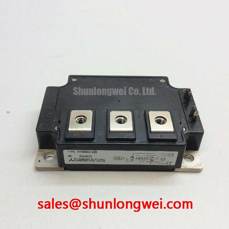
Mitsubishi CM300DU-12H | A High-Reliability Dual IGBT Module for Demanding Power Conversion
The Mitsubishi CM300DU-12H is a 600V, 300A dual IGBT module engineered for exceptional reliability and performance in high-power industrial applications. As a cornerstone of Mitsubishi's H-Series, this module encapsulates proven technology in a robust package, offering designers a dependable solution for power switching circuits.
- High Current Capability: Delivers a continuous collector current (DC) of 300A, making it ideal for high-power inverters and converters.
- Optimized for Low Frequency: Tailored for switching frequencies up to ~15 kHz, balancing conduction and switching losses for maximum efficiency in applications like motor drives.
- Integrated Half-Bridge: Features a dual (2-in-1) configuration, simplifying the design of half-bridge or full-bridge topologies.
- Robust Construction: Built with an isolated baseplate for simplified thermal management and enhanced electrical safety.
Application Scenarios & Engineering Value
The CM300DU-12H is not a general-purpose component; it is a specialized tool engineered to solve specific challenges in industrial power electronics. Its primary value is realized in systems where durability and consistent performance under heavy loads are non-negotiable.
- Variable Frequency Drives (VFDs): In industrial motor control, the module's low saturation voltage (Vce(sat)) directly translates to lower conduction losses, improving the overall efficiency of the drive. Its robust Safe Operating Area (SOA) provides the resilience needed to handle the inductive loads and potential overcurrent conditions common in motor applications.
- Uninterruptible Power Supplies (UPS): For commercial and industrial UPS systems, reliability is paramount. The proven design of the H-Series ensures long operational life, while the module's thermal characteristics allow for stable performance during extended on-battery operation, safeguarding critical infrastructure.
- Welding Power Supplies: The high current handling and short-circuit withstand capability are critical in welding applications. The CM300DU-12H provides the raw power and ruggedness required to manage the demanding, cyclical loads of arc welding processes. For more on preventing component stress, see our guide on IGBT failure analysis.
Key Electrical Characteristics (Tj = 25°C)
The following parameters are critical for design engineers evaluating the CM300DU-12H for their specific application. For a complete overview of its performance curves and thermal characteristics, download the official datasheet.
| Parameter | Symbol | Value |
|---|---|---|
| Collector-Emitter Voltage | VCES | 600V |
| Collector Current (DC) | IC | 300A |
| Collector-Emitter Saturation Voltage (at IC=300A) | VCE(sat) | 2.7V (Max) |
| Total Power Dissipation (per element) | PC | 1130W |
| Junction-to-Case Thermal Resistance (IGBT) | Rth(j-c) | 0.11 °C/W (Max) |
Technical Deep Dive: The Foundation of Reliability
The exceptional performance of the CM300DU-12H is rooted in Mitsubishi's advanced chip and packaging technology. It utilizes a planar structure combined with Carrier Stored Trench-Gate Bipolar Transistor (CSTBT™) principles. This design achieves a highly favorable trade-off between VCE(sat) and switching speed, which is a key differentiator from earlier generation IGBTs. The result is a device that minimizes heat generation during the on-state, a critical factor in high-current applications. This focus on reducing conduction losses is a deliberate design choice, making it a superior option compared to devices optimized purely for high-frequency switching in applications below 15 kHz. For a broader comparison of power semiconductor technologies, explore our guide on IGBT vs. MOSFET vs. BJT.
Engineer's FAQ
1. Can the CM300DU-12H be paralleled for higher current applications?
Yes, it is possible to parallel these modules. However, successful paralleling requires careful attention to symmetrical PCB layout to equalize stray inductances and ensure uniform current sharing. The positive temperature coefficient of VCE(sat) in Mitsubishi's IGBTs provides a degree of self-balancing, but layout and gate drive design remain critical for reliable operation.
2. What is the recommended gate drive voltage?
The standard recommended gate drive voltage for this series is +15V for turn-on and -10V to -15V for turn-off. Using a negative gate voltage is crucial for ensuring a hard turn-off, preventing parasitic turn-on from Miller capacitance (dV/dt effects), and improving noise immunity, which is essential in electrically noisy industrial environments.
For detailed application support or to discuss sourcing for your next project, please contact our technical team.