In the world of modern power electronics, choosing the right switching device is critical to your project’s success. The Insulated Gate Bipolar Transistor (IGBT), Metal-Oxide-Semiconductor Field-Effect Transistor (MOSFET), and Bipolar Junction Transistor (BJT) are the three dominant technologies, but their characteristics are vastly different.
Are you struggling to decide between an IGBT and a MOSFET for a high-voltage motor drive? Or wondering why BJTs are almost never seen in high-speed switching power supplies?
This definitive guide will resolve all your uncertainties. We will conduct a deep dive into the core parameters and key application scenarios for these three devices, and look ahead to the future landscape shaped by emerging technologies like Silicon Carbide (SiC) and Gallium Nitride (GaN).
Core Parameter Comparison: IGBT vs. MOSFET vs. BJT at a Glance
To intuitively understand the differences, let’s start with a detailed table comparing their key performance metrics.
| Parameter | IGBT (Insulated Gate Bipolar Transistor) | MOSFET (Metal-Oxide-Semiconductor Field-Effect Transistor) | BJT (Bipolar Junction Transistor) |
|---|---|---|---|
| Full Name | Insulated Gate Bipolar Transistor | Metal-Oxide-Semiconductor Field-Effect Transistor | Bipolar Junction Transistor |
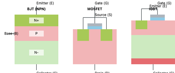
| Terminals | Collector (C), Emitter (E), Gate (G) | Drain (D), Source (S), Gate (G) | Collector (C), Emitter (E), Base (B) |
| Control Method | Voltage-Controlled (Voltage applied to Gate) | Voltage-Controlled (Voltage applied to Gate) | Current-Controlled (Requires continuous Base current) |
| Typical Voltage/Current | High Voltage, High Current (400V – 6kV, 5A – 4500A) | Low to Medium Voltage (Typ. < 250V, HV types up to 1200V) | Can handle higher V/I, but with low gain |
| Switching Speed | Medium (1 – 20 kHz), faster than BJT, slower than MOSFET | Extremely Fast (Up to MHz range) | Slowest |
| On-State Voltage Drop | Very low Vce(sat), ideal for high currents | Rds(on) is very low at low voltages, increases significantly at high voltages | Vce(sat) is low, but overall efficiency is worse than MOSFET |
| Drive Power | Minimal, voltage-driven, high input impedance | Minimal, voltage-driven, high input impedance | Significant, current-driven, requires substantial base current |
| Thermal Performance | High thermal efficiency, relatively lower cooling needs | Highly sensitive to temperature, often needs an extra heat sink | High heat generation, often requires a large heat sink |
How to Choose: A Deep Dive into Key Application Scenarios
Theoretical parameters must ultimately serve practical applications. Understanding “when to choose which device” is a core engineering skill.
When to Choose IGBT? — The King of High-Voltage, High-Current Applications
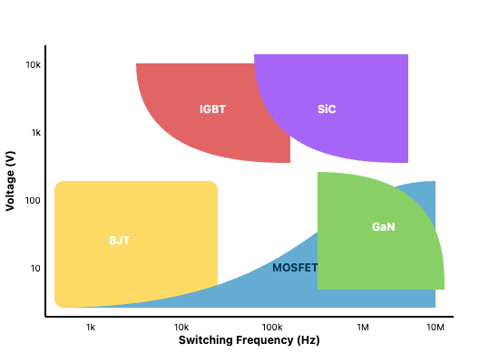
When your application requires both high voltage (> 400V) and high current, with a switching frequency in the low to medium range (1-20 kHz), the IGBT is the undisputed choice. Its excellent low on-state loss and high current density give it superior efficiency in high-power scenarios.
Typical Applications:
- Electric Vehicles (EVs): Traction inverters driving the main motor. Ex: Product page for an Infineon automotive-grade IGBT module.
- Industrial Motor Drives: Variable Frequency Drives (VFDs) for large industrial motors.
- Renewable Energy: Large-scale grid-tied inverters for solar and wind power.
- Uninterruptible Power Supplies (UPS): Backup power for large data centers and industrial facilities.
- Railway Traction: Power systems for high-speed trains and subways.

When to Choose MOSFET? — The Go-To for High-Frequency, High-Efficiency Switching
When your application involves low voltage (< 250V) and demands extreme switching speeds (> 100 kHz, even into the MHz range), the MOSFET is the preferred choice. Its incredibly fast switching speed and ultra-low on-state resistance at low voltages Learn more in “A Deep Dive into MOSFET Rds(on) enable extremely high conversion efficiency in high-frequency applications.
Typical Applications:
- Switched-Mode Power Supplies (SMPS): Core components in computers, servers, and consumer electronics. Ex: STMicroelectronics Power MOSFET product family page.
- DC-DC Converters: Efficiently converting between different DC voltage levels.
- Power Amplifiers: For audio and radio frequency (RF) applications.
- Low-Voltage Motor Control: Motor drives for small devices like drones and robots.
The Status and Use of BJTs
As the earliest transistor, the BJT has been largely replaced by IGBTs and MOSFETs in modern power conversion designs. The complexity of its current-driven nature, slower switching speed, and lower power gain make it difficult to meet today’s demands for high efficiency and high power density. However, it can still be found in some extremely cost-sensitive, low-performance small-signal amplification circuits.
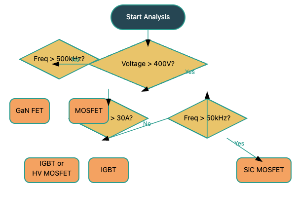
Selection Decision Flowchart
To help you make a quick decision, refer to the following flowchart:
Future Outlook: The Rise of SiC & GaN vs. the Continued Evolution of IGBTs
In recent years, Wide-Bandgap (WBG) semiconductors, represented by Silicon Carbide (SiC) and Gallium Nitride (GaN), are profoundly changing the field of power electronics.
SiC (Silicon Carbide) MOSFET: The Disruptor for Next-Gen High-Voltage Applications
With its higher breakdown voltage, lower losses, and superior thermal performance, SiC is becoming the new favorite for high-voltage (especially >1200V) applications. It is seen as a direct upgrade to the IGBT in certain domains.
- Core Advantages: Much lower switching losses than IGBTs, leading to higher efficiency and smaller system size. How SiC Technology is Empowering the Next Generation of EVs
- Key Applications: Gradually replacing IGBTs in EV main inverters to increase driving range, and widely used in high-end solar inverters and grid infrastructure.
- Current Challenges: Raw material and manufacturing costs are significantly higher than traditional silicon-based IGBTs.
GaN (Gallium Nitride) FET: The Future of High-Frequency, High-Density Power
GaN devices are known for their unparalleled switching speed (>100 V/ns) and extremely low switching losses, making them a key technology for achieving ultimate power density. They primarily target low-to-medium voltage (up to ~650V) high-frequency applications.
- Core Advantages: Extremely high switching frequency allows for a drastic reduction in the size of passive components like inductors and capacitors, enabling converters with very high power density.
- Key Applications: Consumer electronics fast-charging adapters (USB-C PD), data center power supplies, EV on-board chargers (OBCs), and high-end audio amplifiers. Ex: GaN Systems Gallium Nitride transistor application notes.
- Current Challenges: Extremely sensitive to parasitic inductance in the circuit, requiring advanced packaging and PCB layout techniques. PCB Layout Design Guide for GaN Devices
Conclusion: There’s No ‘Best’ Device, Only the ‘Right’ Choice
The world of power semiconductors has no one-size-fits-all solution.
- IGBTs remain the champions of the medium-frequency, high-voltage, high-current industrial and transportation sectors.
- MOSFETs dominate in low-voltage, high-frequency switching applications.
- SiC and GaN represent the future, not as simple replacements, but as complementary technologies that push the boundaries of power electronics performance.
Ultimately, technology selection is a trade-off between performance, cost, supply chain maturity, and design complexity.
Frequently Asked Questions (FAQ)
Q1: What is the main difference between an IGBT and a MOSFET?
A1: A simple rule of thumb: IGBTs excel at “high power” (high voltage, high current), while MOSFETs excel at “high frequency” (fast switching).
Q2: Why is a MOSFET’s switching speed faster than an IGBT’s?
A2: A MOSFET is a unipolar device (conduction by electrons only), so it turns off quickly. An IGBT is a bipolar device (conduction by both electrons and holes). During turn-off, it takes extra time to remove the excess holes, creating a “tail current” that slows it down.
Q3: Will SiC and GaN completely replace silicon IGBTs?
A3: They won’t completely replace them; it’s more of a complementary evolution. Silicon IGBTs will retain a huge advantage in cost-sensitive, mature applications.
Q4: My application needs 1000V, 50A, and a 15kHz switching frequency. What should I use?
A4: This is a classic application area for an IGBT, offering the best cost-performance ratio. If you have an ample budget and are pursuing maximum efficiency, a SiC MOSFET is a viable alternative. .