

Content last revised on June 23, 2026
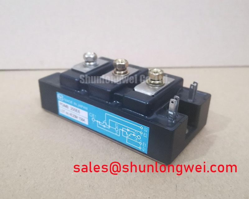
NIEC PDMB 200E6 | High-Integration 7-in-1 PIM for Compact Motor Drives
The NIEC PDMB 200E6 is an intelligently engineered Power Integrated Module (PIM) designed to solve a core challenge in modern power electronics: maximizing functionality within a minimal footprint. This 600V, 200A module is not just a component; it's a system-level solution, integrating a three-phase converter, a three-phase inverter, and a brake chopper into a single, thermally efficient package. It represents a pragmatic choice for engineers developing cost-sensitive and space-constrained motor control applications where reliability and manufacturing velocity are non-negotiable.
Application Suitability and Engineering Value
The true value of the PDMB 200E6 is revealed in its application-specific benefits. Its design directly addresses the pain points encountered in the development of compact industrial drives.
- Variable Frequency Drives (VFDs): For low-to-mid-power Variable Frequency Drive (VFD) systems, this PIM is a game-changer. By consolidating seven functional blocks, it drastically reduces PCB complexity, slashes assembly time, and minimizes potential points of failure associated with discrete component layouts. The result is a more robust and cost-effective manufacturing process.
- Robotic Servo Drives: Precision and dynamic response are paramount in robotics. The integrated brake chopper in the PDMB 200E6 is critical for managing regenerative energy during rapid deceleration, ensuring positional accuracy and protecting the DC bus. This integration simplifies the design of compact and reliable robotic servo drives without needing an external braking circuit.
- General-Purpose Inverters: In applications like pumps, fans, and conveyor systems, long-term reliability is key. The NIEC PDMB 200E6 provides a proven, field-tested foundation, simplifying the supply chain and creating a more predictable thermal and electrical system for high-efficiency inverter ACs.
Key Parameter Overview for System Designers
The following table provides essential data for design-in and simulation. These parameters underscore the module's suitability for a wide range of industrial motor control tasks.
| Parameter | Value |
|---|---|
| Collector-Emitter Voltage (VCES) | 600 V |
| Continuous Collector Current (IC) @ TC=80°C | 200 A |
| Collector-Emitter Saturation Voltage (VCE(sat)) @ IC=200A | 2.7 V (Typ.) |
| Forward Voltage Drop, FWD (VF) @ IF=200A | 2.2 V (Typ.) |
| Forward Voltage Drop, Rectifier (VF) @ IF=200A | 1.5 V (Typ.) |
| Isolation Voltage (Viso) | 2500 V (AC, 1 minute) |
For a comprehensive list of all electrical and thermal characteristics, you can download the official PDMB 200E6 datasheet.
Technical Deep Dive: The 7-in-1 PIM Advantage
The term PIM (Power Integrated Module) refers to the intelligent consolidation of multiple power stages. The NIEC PDMB 200E6 is a prime example of this philosophy. Internally, it houses a complete drive front-end and output stage: a three-phase diode bridge rectifier, a robust three-phase IGBT inverter bridge with anti-parallel freewheeling diodes (FWDs), and a dedicated IGBT/FWD pair for the dynamic brake chopper. This level of integration delivers three critical engineering advantages:
Frequently Asked Questions (FAQ)
Is an integrated PIM like the PDMB 200E6 always better than a discrete solution?
For low-to-mid-power motor drives (typically up to 30-40kW), the PIM approach offers a superior total cost of ownership. While the upfront cost of the module may be higher than the sum of individual discrete components, the significant savings in PCB real estate, assembly labor, procurement complexity, and design time often result in a more competitive end product. The trade-offs between integrated and discrete solutions become more nuanced at higher power levels, but for the target applications of the PDMB 200E6, integration is a clear winner.
How should I approach the gate drive design for this module?
While the PDMB 200E6 simplifies the power stage, a robust gate drive is still crucial. Due to the integrated nature, it is vital to ensure good layout practices to minimize cross-talk between the inverter and brake chopper gate signals. A driver with a short-circuit protection feature (desaturation detection) and the capability to provide a slight negative gate voltage during the off-state is highly recommended to ensure noise immunity and prevent spurious turn-on. For further questions on your specific application, please contact our technical team for expert guidance.