

Content last revised on October 18, 2026
LMG7550XUFC Display Identification and Inspection
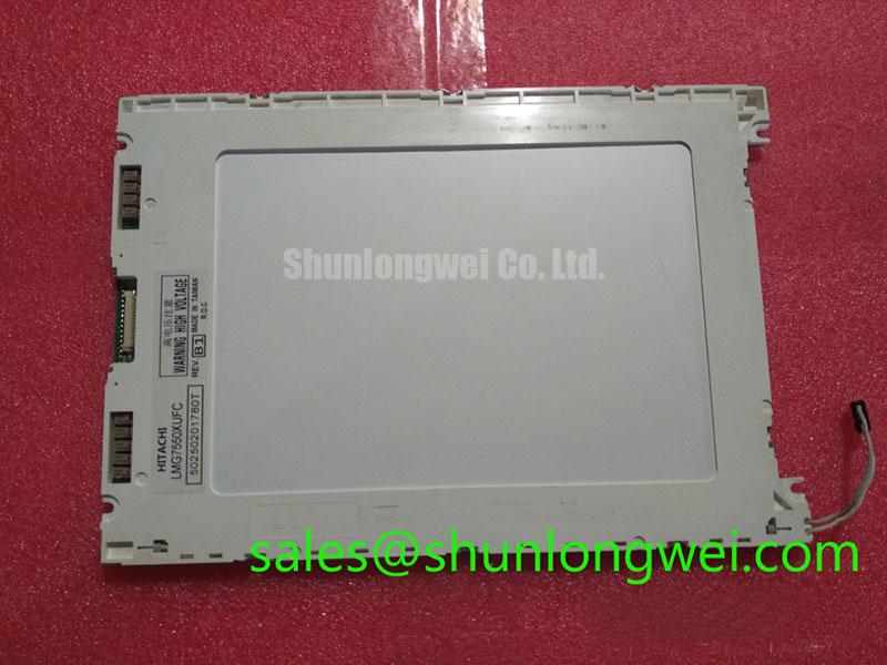
Check the instrument with power isolated, inspect the panel bezel and connector area for dust ingress or uneven compression, then compare the installed display marking with LMG7550XUFC. This unit is identified as a Hitachi / KOE LCD panel. The exact panel technology, electrical interface, bias requirements, backlight arrangement, and mechanical drawing should be matched with the original panel documentation before energizing a replacement.
For precision electronic test and measurement instruments, display readability depends on more than the liquid crystal cell. The enclosure aperture, polarizer condition, backlight circuit, bias stability, connector integrity, and temperature behavior all influence whether characters remain uniform and legible. Engineers evaluating this panel should also compare connector orientation, mounting points, viewing direction, and controller timing with the existing assembly. A reference such as LM64C08P can support a compatibility review, but it should not be treated as an automatic substitute without an electrical, optical, and mechanical comparison.
Polarizer Discoloration, Adhesive Aging, and UV Degradation
Inspect contrast loss under the actual illumination used by the instrument rather than relying only on a bench lamp. FSTN and STN monochrome panels can show a visibly different reflective response when the polarizer, adhesive layer, or front bezel has aged. Look for yellowing, localized haze, edge bubbles, silvering, and areas that change appearance when the viewing angle shifts. These observations help separate optical aging from a controller or backlight fault.
Legacy terminals exposed to ultraviolet radiation, elevated enclosure temperature, or cleaning vapors may develop adhesive discoloration or bubbling. Such defects can scatter ambient light and reduce the apparent black level, especially on instruments used near bright work lights. A practical inspection should compare the center, corners, and seal perimeter while displaying the same text pattern. A screen photograph taken before disassembly is useful for recording nonuniformity without presenting it as a quantified panel specification.
When an older assembly uses a fluorescent backlight, the ignition circuit requires controlled high voltage and adequate creepage. As a Design Consideration, legacy CCFL systems may require a cold striking voltage in the approximate 1200 to 1600 Vrms range, while the sustained lamp voltage can be lower. These values describe a possible inverter environment, not a confirmed rating of LMG7550XUFC. The service fixture should keep the ballast transformer, lamp leads, conductive bezel parts, and grounded metalwork arranged to limit corona and unintended discharge. The system integrator must verify the actual backlight technology and inverter requirements from the original equipment documentation.
Reflective contrast should be checked after the enclosure is fully assembled. A loose gasket or a changed bezel depth can admit stray light and create an optical impression similar to polarizer degradation. If the replacement assembly uses optical bonding, its moisture resistance, adhesive compatibility, and service method should be confirmed independently; the available product identity does not establish those construction features for this panel.
CCFL Inverter Strike Failure Localization: Tube Aging vs. Inverter Faults
Separate the display cell from the illumination fault by observing whether the character pattern remains stable while brightness changes. A dark screen with visible response under angled ambient light can point the technician toward the backlight path, whereas unstable characters or missing segments require attention to the panel drive and connector interface. This distinction is particularly useful in precision measurement equipment where a dim display may be mistaken for a contrast failure.
For a legacy CCFL installation, compare the inverter behavior at cold start and after warm operation. A lamp that takes longer to strike, flashes unevenly, or causes repeated inverter restarting may reflect tube aging, insulation stress, ballast transformer leakage, or switching transistor damage. These conditions should be assessed with an instrument rated for the applicable high voltage. Do not connect an ordinary oscilloscope probe directly to the lamp circuit.
As a Design Consideration, some CCFL inverter arrangements use an ignition region around 1200 to 1600 Vrms, a sustained operating region around 300 to 600 Vrms, and regulated lamp current near 5 mA. These are illustrative operating ranges, not factory specifications assigned to LMG7550XUFC or acceptance limits for its backlight. The replacement decision should be based on the original backlight assembly, connector pinout, ballast topology, and measured operating behavior.
Check the contrast-bias rail separately from the lamp circuit. In many monochrome LCD assemblies, the Vee supply or V0 contrast input influences contrast and can be disturbed by inverter switching noise. A Design Consideration for legacy equipment is a negative rail in the approximate −15 V to −24 V range, with filtering arranged to prevent visible modulation in text. The actual rail polarity and value must follow the equipment schematic. A related system review may include the LM32K071 display solution reference, without implying electrical or mechanical compatibility.
Contrast Ratio Potentiometer Calibration and Thermistor Feedback Regulation
Adjust the contrast control only after the panel has reached the temperature and illumination conditions found in service. Turning the potentiometer to compensate for an unstable V0 rail can make the characters appear acceptable briefly while reducing operating margin elsewhere. Record the adjustment position, display temperature, and supply behavior before changing the calibration point.
Where thermal compensation is fitted, evaluate it by displaying fine text, isolated segments, and full character blocks. A thermistor network that has drifted, lost contact, or been affected by connector oxidation may create contrast washout at one temperature and excessive background darkness at another. Inspect the sensor location and wiring as a circuit function, not as an assumed feature of the LCD panel itself.
As a Design Consideration, keeping negative bias ripple below approximately 20 mV peak to peak may be appropriate for a sensitive contrast circuit, but the acceptable limit belongs to the complete display electronics and measurement method. Verify ripple at the panel interface with suitable probing, because switching current from a fluorescent inverter can produce a different result at the power supply than at the LCD connector. When integrating the panel into a replacement front end, designers should also confirm power sequencing against the panel and controller documentation. Correct sequencing helps avoid unintended drive conditions during startup or power-down.
Long static test screens should be included in a preventive maintenance routine. A monochrome LCD may retain a temporary visual impression after prolonged fixed content, while a permanent defect requires a broader investigation of the cell, drive waveform, temperature, and mechanical stress. The display should be checked with changing text and contrast levels before a service decision is made. ⚠️ Maintenance Note: inspect the cabinet airflow path and bezel sealing gasket during scheduled service so heat and dust do not compound contrast drift or optical contamination.
For wider industrial display integration guidance covering enclosure sealing, viewing conditions, and service testing, consult Industrial Display & HMI Solutions. Optical processing terms such as tone mapping belong to the host system rather than the LCD panel; background reference is available in Tone Mapping. If the instrument exchanges measurements through a PLC network, the display content may also depend on the host communication layer, including Modbus.
Elastomeric Zebra Strip Connector Compression & Heat-Seal (HSC) Interconnect Integrity
Missing rows, columns, or intermittent characters should be investigated at the panel interface before changing contrast calibration. First identify the actual interconnect construction; the following checks apply only where the corresponding connector type is present. For a serviceable elastomeric connection, remove power, release the bezel evenly, and inspect the connector path for skew, contamination, oxidation, compression marks, or displacement caused by vibration. The conductive strip must remain aligned with the panel electrode pattern and the controller board contacts throughout the bezel’s full clamping area.
Uneven clamping can produce localized response changes that resemble a damaged LCD segment. The correct compression depends on the connector material, contact geometry, frame design, and supplier assembly method; use the assembly documentation rather than a generic pressure target. Apply force uniformly rather than tightening one side fully before the opposite side.
Heat-seal connections require a different service approach from removable zebra strips. Inspect the bonded edge for lifting, creasing, contamination, or localized stress from the metal frame. Rework temperature, dwell time, tooling pressure, and alignment are process parameters that must come from the connector or panel assembly documentation. Repeated heating without process control can damage the seal or distort the display edge.
For instruments exposed to vibration or repeated enclosure access, verify that any FPC bend path is free from sharp folds and that any connector lock is fully engaged. The panel’s dimensions and mounting arrangement should be matched against the original mounting aperture so the bezel does not transfer housing distortion into the glass. Final testing should include cold startup, warm operation, contrast adjustment, static text, changing characters, and a gentle enclosure vibration check while monitoring for intermittent rows or columns.