


Content last revised on February 3, 2026
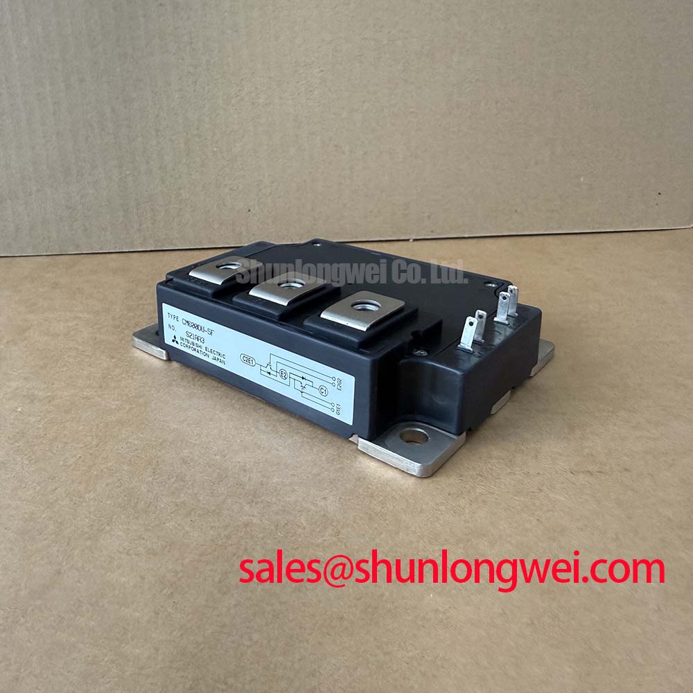
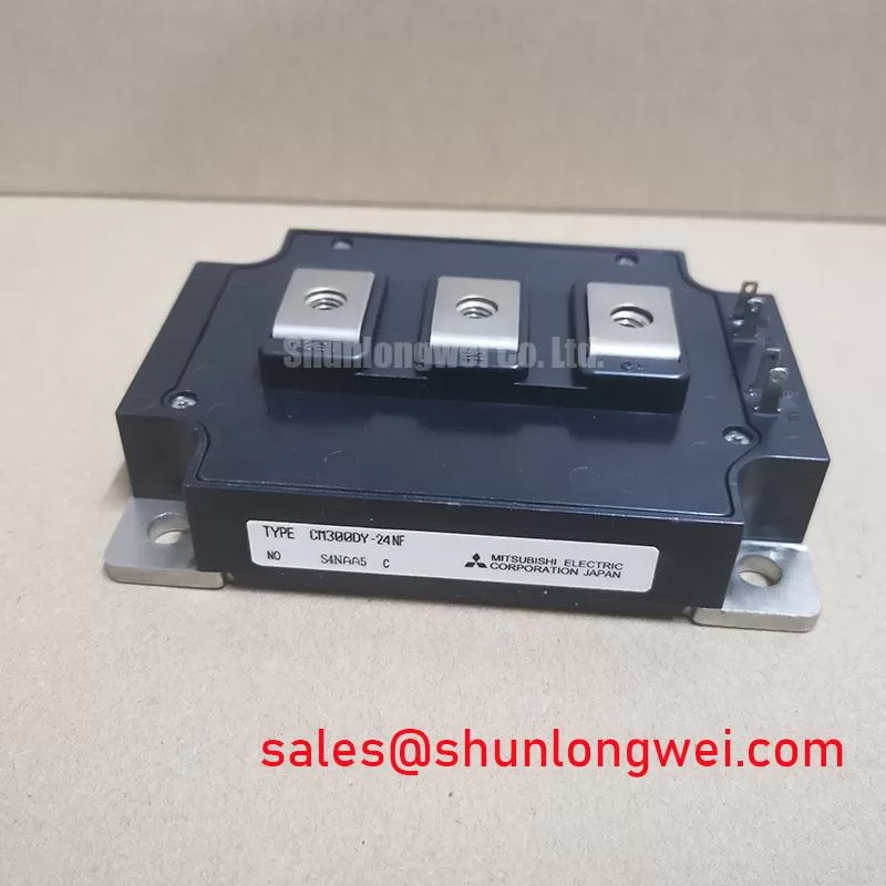
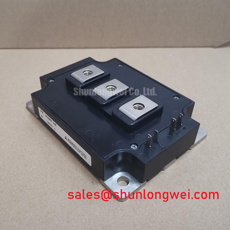
CM300DY-24NF: Dual 1200V/300A IGBT Module
A Foundation for High-Current Power Conversion
The CM300DY-24NF is a high-power dual IGBT module engineered for demanding switching applications, delivering a robust platform for designers of industrial inverters, servo drives, and uninterruptible power supplies. It establishes a strong performance baseline with its core specifications: 1200V collector-emitter voltage | 300A continuous collector current | VCE(sat) of 2.7V. This module is built for efficiency, featuring a low saturation voltage to minimize conduction losses. Its design also ensures straightforward thermal management through an electrically isolated baseplate. For engineers developing power stages for AC motor control up to 150 kW, the CM300DY-24NF provides a well-documented and reliable solution to manage substantial power flow efficiently.
Key Parameter Overview
Decoding Electrical and Thermal Specs for High-Reliability Designs
The technical specifications of the CM300DY-24NF underscore its suitability for high-power industrial applications. The parameters detailed below are critical for accurate system modeling, thermal design, and ensuring operational reliability under demanding load cycles.
| Parameter | Symbol | Value | Conditions |
|---|---|---|---|
| Collector-Emitter Voltage | VCES | 1200V | VGE = 0V |
| Collector Current (DC) | IC | 300A | TC = 25°C |
| Collector-Emitter Saturation Voltage | VCE(sat) | 2.7V (Typ.) / 3.2V (Max.) | IC = 300A, VGE = 15V, Tj = 125°C |
| Thermal Resistance (Junction to Case) | Rth(j-c)Q | 0.083 °C/W | Per IGBT |
| Maximum Junction Temperature | Tj(max) | 150°C | - |
| Isolation Voltage | Viso | 2500Vrms | AC 1 minute |
Download the CM300DY-24NF datasheet for detailed specifications and performance curves.
Application Scenarios & Value
System-Level Value in Motor Drives and Power Conversion Systems
The CM300DY-24NF is strategically positioned for designers of three-phase industrial systems who need a reliable, high-current switching component. Its dual-IGBT half-bridge configuration is a fundamental building block for Variable Frequency Drives (VFDs), AC servo controllers, and general-purpose inverters. In a VFD application, for instance, a critical challenge is managing heat generated by conduction and switching losses, which directly impacts the required heat sink size and enclosure volume. The module's VCE(sat) of 2.7V at a nominal 300A and Tj of 125°C directly translates to lower conduction losses compared to older generation IGBTs. This reduction in waste heat simplifies the heat sink design, potentially allowing for a smaller, more cost-effective cooling solution and contributing to a lower Total Cost of Ownership (TCO).
What is the primary benefit of its low VCE(sat)? Reduced conduction losses, leading to higher system efficiency. The integrated fast-recovery freewheeling diode is optimized to work in tandem with the IGBT, minimizing switching losses, particularly in motor drive applications that rely on high PWM frequencies for precise control. This module provides a robust foundation for systems where reliability and thermal performance are paramount. For systems requiring a lower current rating but similar voltage characteristics, the related CM200DY-24NF offers a 200A alternative within the same NF-Series.
Frequently Asked Questions
What is the primary function of the half-bridge configuration in the CM300DY-24NF?
The half-bridge (dual) configuration provides two IGBTs in a single module, which is the essential topology for creating one phase of a three-phase power inverter. Using three of these modules allows a designer to efficiently build a complete three-phase bridge for applications like AC motor control.
How does the Rth(j-c) of 0.083 °C/W per IGBT impact thermal design?
The thermal resistance from junction to case (Rth(j-c)) is a critical metric for thermal management. A low value like 0.083 °C/W signifies efficient heat transfer from the silicon chip to the module's baseplate. This allows the heat sink to dissipate heat more effectively, keeping the junction temperature below the 150°C maximum and ensuring long-term reliability. Think of it as a wider pipe for heat to escape—the wider the pipe, the less pressure (temperature) builds up inside.
Is an external gate driver required for the CM300DY-24NF?
Yes, this is a standard IGBT module that requires an external gate drive circuit. The gate driver is responsible for providing the precise voltage and current pulses (typically +15V for turn-on, -5V to -15V for turn-off) needed to switch the IGBTs efficiently and protect against issues like parasitic turn-on. You can find detailed gate drive requirements in resources like this guide to robust gate drive design.
What does the 'NF' designation in the part number signify?
The 'NF' typically denotes a specific series or generation from Mitsubishi, often characterized by a particular balance of performance features like low saturation voltage (VCE(sat)) and switching speed, making it suitable for a range of industrial applications.
Technical Deep Dive
An Analysis of VCE(sat) and its Impact on Operational Efficiency
A key performance indicator for an IGBT module in a high-current application is its collector-emitter saturation voltage, VCE(sat). For the CM300DY-24NF, the typical VCE(sat) is specified at 2.7V under a 300A load at a junction temperature of 125°C. This parameter is the direct source of conduction loss, calculated as P_cond = VCE(sat) * IC. A lower VCE(sat) means less power is converted into heat during the 'on' state of the switch.
To put this into perspective, imagine two water pipes of the same diameter trying to carry the same amount of water (current). One pipe has a smooth inner surface (low VCE(sat)), while the other is rough (higher VCE(sat)). The pump has to work harder to push water through the rough pipe, wasting energy as friction (heat). Similarly, the lower VCE(sat) of the CM300DY-24NF reduces the electrical "friction," improving overall inverter efficiency. This is especially crucial in applications like uninterruptible power supplies (UPS) and solar inverters, where every percentage point of efficiency gained translates directly to lower operating costs and better energy delivery.
The strategic value of this low conduction loss lies in its downstream effects on system design. A more efficient power stage generates less waste heat, which can lead to a reduction in the size, weight, and cost of the required cooling system. This enables the design of more compact, power-dense inverters without compromising on long-term reliability, a critical consideration in modern industrial automation. For a deeper understanding of how this metric fits into the broader picture, exploring concepts like the balance between voltage, current, and thermal management is essential for any power electronics engineer.