Content last revised on November 19, 2025
FF200R12KE3 IGBT Module: Technical Analysis for High-Reliability Power Systems
Engineering an Efficient and Reliable Core for Power Conversion
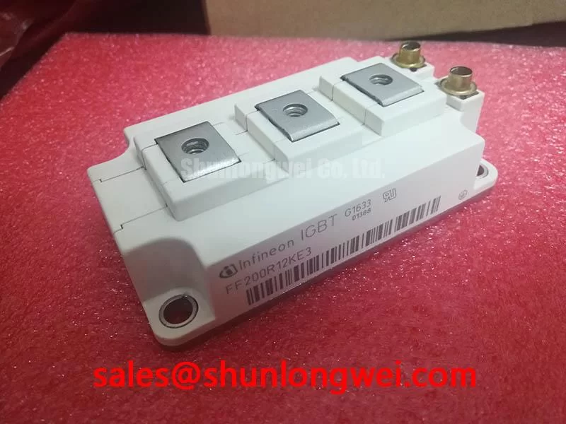
The FF200R12KE3 is a 1200V, 200A dual IGBT module engineered for high-efficiency and reliable operation in demanding power conversion systems. Leveraging Infineon's proven TRENCHSTOP™ IGBT3 technology, this module provides a robust foundation for applications like industrial motor drives and solar inverters. Its key specifications include: 1200V Collector-Emitter Voltage | 200A DC Collector Current | 175°C Maximum Operating Junction Temperature. This design delivers low conduction losses and excellent thermal performance, directly addressing the challenge of maintaining operational stability under heavy loads. For systems requiring robust thermal management and predictable switching characteristics, the FF200R12KE3 offers a well-documented and dependable solution. Its low collector-emitter saturation voltage (VCE(sat)) makes it a best-fit choice for medium-frequency drive applications where minimizing conduction losses is paramount to achieving target efficiency ratings.
Application Scenarios & Value
System-Level Benefits in Industrial Motor Control and Drives
The FF200R12KE3 is specifically optimized for power conversion stages within industrial applications. Its primary use case is in Variable Frequency Drives (VFDs) and servo drives, which are the backbone of modern factory automation. In a typical VFD controlling a three-phase induction motor, the engineer's challenge is to manage the heat generated during continuous operation, especially under fluctuating load conditions. The module's thermal resistance from junction to case (RthJC) of 0.45 K/W per IGBT is a critical parameter. This value signifies efficient heat transfer away from the silicon chip to the heatsink. Think of it like the thermal conductivity of a CPU cooler's thermal paste; a lower number means less thermal buildup, allowing the system to run cooler and more reliably over its lifespan. This superior thermal performance enables more compact heatsink designs or provides greater thermal headroom in harsh industrial environments. What is the primary benefit of its low VCE(sat)? It directly reduces power dissipation as heat, improving overall system efficiency. For applications demanding higher current capabilities within a similar voltage class, the related FF300R12KE3 provides an increased current rating.
Key Parameter Overview
Decoding the Specs for Efficient Power Switching
The technical specifications of the FF200R12KE3 are tailored for robust performance in high-power switching circuits. The parameters below, sourced from the official manufacturer datasheet, are critical for system design, simulation, and thermal management.
| Parameter | Symbol | Condition | Value | Unit |
|---|---|---|---|---|
| Maximum Ratings | ||||
| Collector-Emitter Voltage | VCES | Tvj = 25°C | 1200 | V |
| Continuous DC Collector Current | IC nom | - | 200 | A |
| Repetitive Peak Collector Current | ICRM | tP = 1 ms | 400 | A |
| Total Power Dissipation | Ptot | TC = 25°C, Tvj max = 175°C | 1000 | W |
| Operating Junction Temperature | Tvj op | - | -40 to +150 | °C |
| IGBT, Inverter - Characteristic Values | ||||
| Collector-Emitter Saturation Voltage | VCE sat | IC = 200 A, VGE = 15 V, Tvj = 25°C | 1.70 (Typ.) | V |
| Gate-Emitter Threshold Voltage | VGE(th) | IC = 8.00 mA, VCE = VGE, Tvj = 25°C | 5.8 (5.0 - 6.5) | V |
| Turn-On Switching Loss | Eon | IC = 200 A, VCE = 600 V, Tvj = 125°C | 37.00 | mJ |
| Turn-Off Switching Loss | Eoff | IC = 200 A, VCE = 600 V, Tvj = 125°C | 46.00 | mJ |
| Diode, Inverter - Characteristic Values | ||||
| Forward Voltage | VF | IF = 200 A, VGE = 0 V, Tvj = 25°C | 1.75 (Typ.) | V |
| Reverse Recovery Energy | Erec | IF = 200 A, VR = 600 V, Tvj = 125°C | 26.00 | mJ |
This data is a summary. For detailed specifications, characteristic curves, and thermal information, please refer to the official document.
Download the FF200R12KE3 datasheet for detailed specifications and performance curves.
Frequently Asked Questions (FAQ)
How does the VCE(sat) of 1.70V impact the thermal design in motor control applications?A lower VCE(sat) directly translates to lower conduction power loss (Ploss = VCE(sat) * IC). For a 200A load, this characteristic minimizes the heat generated by the IGBT itself, simplifying the thermal management system. This allows designers to potentially use smaller, more cost-effective heatsinks or operate at a higher ambient temperature without exceeding the maximum junction temperature, thus improving overall system reliability.
What is the significance of the 175°C maximum operating junction temperature (Tvj max)?While the standard operating temperature is up to 150°C, the 175°C maximum rating provides a crucial safety margin. It allows the module to withstand temporary temperature overshoots that might occur during fault conditions or peak load events in a demanding industrial environment, enhancing the robustness and longevity of the end-system.
Is the FF200R12KE3 suitable for high-frequency switching applications?The FF200R12KE3 utilizes TRENCHSTOP™ IGBT3 technology, which represents a balance between low conduction losses and switching losses. While it performs exceptionally well in applications with switching frequencies up to around 20 kHz, such as standard motor drives, for very high-frequency designs (e.g., >50 kHz), a different IGBT technology might offer lower Eon and Eoff values for optimized efficiency.
Empowering Your Design
The FF200R12KE3 provides a solid, industry-proven foundation for developing reliable and efficient power conversion systems. Its well-balanced electrical and thermal characteristics allow engineers to meet performance targets with confidence. For further technical inquiries or to discuss how this component fits within your specific design architecture, please review the official datasheet or contact our technical support team for assistance.

