

Content last revised on October 2, 2026
Sharp LQ190E1LX77 Industrial TFT LCD Panel
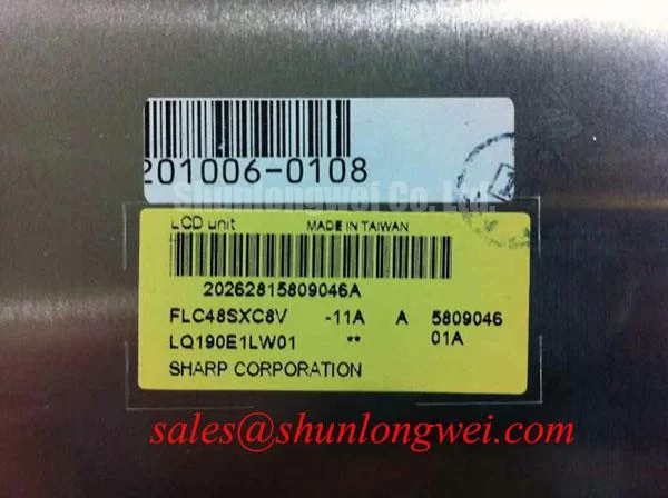
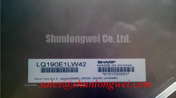
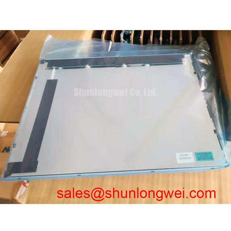
Begin a replacement inspection by comparing the original panel label, connector arrangement, mounting frame, and visible optical condition with the proposed Sharp LQ190E1LX77 unit. The documented product identity is an Industrial Grade LCD/HMI Panel supplied as a TFT-LCD Display Module by Sharp. Its specification status is recorded as Official Factory Spec Verified; system-specific electrical values not included in the available factory data should be confirmed from the original equipment documentation before installation.
This approach is important for maintenance teams working on operator terminals, telematics consoles, and industrial control displays. A panel can have the correct diagonal class yet remain electrically incompatible if the host system expects a different interface, timing arrangement, backlight control method, or connector orientation. The LQ190E1LX77 should therefore be evaluated as a complete display-module replacement against the removed unit, not by enclosure size alone.
| Item | Documented information |
|---|---|
| Model | LQ190E1LX77 |
| Manufacturer | Sharp |
| Product category | Industrial Grade LCD/HMI Panel |
| Construction category | TFT-LCD Display Module |
| Specification status | Official Factory Spec Verified |
The available product record does not establish a confirmed supply voltage, pinout, resolution, luminance rating, viewing angle, touch technology, backlight topology, operating temperature range, or connector specification. Those values should not be inferred from the model number. When integrating the panel into a control cabinet or vehicle display console, designers should verify each value against the equipment service manual and the original panel documentation.
Optical Luminance Degradation and Backlight Retrofit Assessment
Inspect the removed display in a controlled environment before deciding whether a fault is located in the LCD module, the backlight circuit, or the host display controller. Record whether the screen is completely dark, faintly visible under an external lamp, uneven across the viewing area, or affected by intermittent illumination during cabinet movement. These observations help separate image-generation faults from illumination faults, but they do not by themselves identify a single failed component.
The available factory information for the LQ190E1LX77 does not confirm whether its original backlight is CCFL or LED, nor does it specify an approved retrofit path. A replacement engineer should not assume that a constant-current LED driver can be connected to this module without checking the original backlight connector, enable signal, current requirement, protection behavior, and mechanical light source arrangement. Any CCFL-to-LED modernization should be treated as a system modification requiring optical, electrical, thermal, and electromagnetic validation.
For a field replacement, compare the host controller’s video interface with the original panel before applying power. Verify connector keying, signal naming, differential-pair assignment, timing requirements, display-enable behavior, and power sequencing from the equipment documentation. If the display is used near servo drives or inverter cabling, route high-energy switching conductors separately from display wiring and confirm the final assembly under the actual machine operating state.
When a panel shows intermittent brightness or a black screen, technicians should check the backlight enable path, connector retention, harness strain, supply behavior during startup, and any protection or fault output provided by the host circuit. An open-circuit or overcurrent indication may originate in the driver, wiring, connector, or lamp assembly. Oscilloscope measurements should be made only with probes and procedures suitable for the circuit under test.
The LM190E08-TLG6 may be reviewed as a separate same-size or same-resolution replacement candidate where the equipment documentation confirms electrical and mechanical compatibility. It should not be treated as a universal substitute solely because the visible panel dimensions appear similar.
Edge-Lit Thermal Management and Optical Surface Preservation
Before fitting the LQ190E1LX77 into a cabinet or heavy-equipment console, inspect the surrounding frame for blocked ventilation paths, compressed sealing material, metal burrs, and pressure points around the display perimeter. Heat generated by the backlight and nearby electronics must be allowed to leave the assembly without transferring concentrated mechanical stress into the panel. The correct thermal arrangement is system-dependent because enclosure volume, ambient temperature, sunlight exposure, and nearby power electronics all affect the result.
The manufacturer information supplied for this product does not confirm an edge-lit LED rail, an aluminum spreader arrangement, a PMMA light-guide construction, an L70 or B50 rating, or a specified half-life. These features should not be assigned to the LQ190E1LX77 without the applicable factory datasheet. When a retrofit uses a different backlight technology, the integrator should verify the optical stack, heat path, driver compatibility, and luminance uniformity after the panel has reached operating temperature.
Thermal checks should compare the display center, bezel edges, driver area, and adjacent cabinet surfaces during representative operation. A localized warm area, brightness gradient, or progressive color shift can justify additional investigation of airflow, mounting contact, backlight drive conditions, or nearby heat sources. The appropriate acceptance limits must come from the equipment design or the applicable panel documentation rather than from a generic LCD assumption.
High-ambient installations also require attention to surface reflections. The available specification does not state an anti-glare or anti-reflective coating, sunlight contrast ratio, or rated luminance for this model. Engineers evaluating the panel for an earthmoving-equipment telematics display should confirm readability at the intended viewing angle and under direct ambient illumination using the actual front window, bezel, and protective cover.
Maintenance Note: Inspect the cabinet airflow path and display sealing material at scheduled service intervals, because dust accumulation or a deteriorated gasket can change both thermal conditions and mechanical support.
For broader enclosure, sealing, vibration, and HMI integration considerations, consult the Industrial Display & HMI Solutions engineering reference. The guide can support system-level review, while model-specific electrical limits still require confirmation from the original documentation.
Preventing Localized Light-Guide Compression and Dark-Field Mura
Mechanical replacement begins with a dry fit. Place the display module into the bezel without tightening fasteners, then check whether the frame contacts the panel evenly around the perimeter. Look for warped sheet metal, uneven gasket thickness, protruding screw heads, and harnesses trapped between the module and its support frame. A display that produces acceptable images on a bench can develop bright edges, dark patches, or uneven fields after installation if the chassis applies localized pressure.
The supplied factory record does not specify the LQ190E1LX77 bezel envelope, mounting-hole tolerances, fastener type, allowable compression, or installation torque. Do not apply a generic M3 torque value as a Sharp factory limit. The system engineer should follow the equipment manufacturer’s fastening procedure and distribute clamping force evenly across the frame. If no procedure is available, a controlled mechanical validation should be completed using the actual bracket, gasket, fasteners, and panel.
Dark-field inspection is useful after the panel has been installed and allowed to stabilize. Display a uniform dark image and inspect the corners, edges, and fastener locations from the normal operator position. Repeat the check after the cabinet has been moved or subjected to the expected equipment vibration profile. A change in mura, pressure mark, or brightness uniformity may indicate an interaction between the panel, bezel, gasket, or harness routing; it should be investigated by controlled mechanical release and reassembly rather than assigned to one cause immediately.
Touch capability must also be verified independently. The available product description identifies a TFT-LCD display module but does not confirm a resistive touch layer, capacitive touch layer, glove operation, water tolerance, controller interface, or touch sensitivity. If the host equipment requires operator input with gloves or in wet conditions, the integrator should verify the touch construction and controller compatibility from the original terminal documentation.
Do not clean the front surface with an unverified solvent or abrasive material. The appropriate cleaning method depends on the installed surface treatment and the equipment maker’s maintenance instructions. A protective window, optical bonding layer, or bezel lip can also alter reflections and touch response, so the complete front assembly should be assessed rather than the bare panel alone.
Dynamic Contrast, Temperature Tracking, and Industrial Signal Integrity
Check the panel image at cold startup, normal cabinet temperature, and after sustained operation while recording the host system’s display behavior. Changes in gray uniformity, response appearance, flicker, or viewing-angle performance can be influenced by panel temperature, controller timing, backlight behavior, cable integrity, or optical reflections. The available factory information does not identify the LQ190E1LX77 cell mode, contrast ratio, viewing cone, response time, gamma characteristics, or temperature limits.
For this reason, the module should not be described as TN, IPS, or MVA without a confirmed factory source. Nor should a specific symmetric viewing angle or direct-sunlight contrast value be assigned to it. Engineers assessing the panel for a mining shovel or earthmoving-equipment telematics display should evaluate the installed unit from the operator’s actual seating position, through the final protective window, and with the cabin lighting and sun position that matter to the application.
Signal integrity is another system-level consideration. The host designer should verify whether the original assembly uses LVDS, TTL, or another display interface, then confirm the required differential routing, termination, connector pinout, clock behavior, and cable shielding. A nominal impedance target or skew limit should be taken from the controller and panel documentation rather than assumed from the product category. In high-EMI environments, minimize unshielded cable length, separate display wiring from switching power conductors, and validate the video waveform at the panel connector under real machine operation.
If the screen is blank while the host appears to boot normally, compare the panel supply, enable state, video activity, and known-good signal path using approved test equipment. A missing image may involve power sequencing, backlight status, cable continuity, connector contact, controller configuration, or panel damage. If the image is present but unstable, inspect grounding, shielding, harness movement, and interference from nearby drives before replacing the module again.
The LQ190E1LX77 is documented here as a Sharp TFT-LCD display module for industrial LCD/HMI evaluation. Final acceptance should be based on verified electrical compatibility, mechanical fit, optical readability, thermal behavior, and the service requirements of the completed equipment rather than on the model designation alone.