Content last revised on October 21, 2026
M185XW01 VF Identification and Replacement Checks
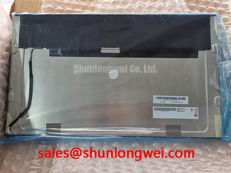
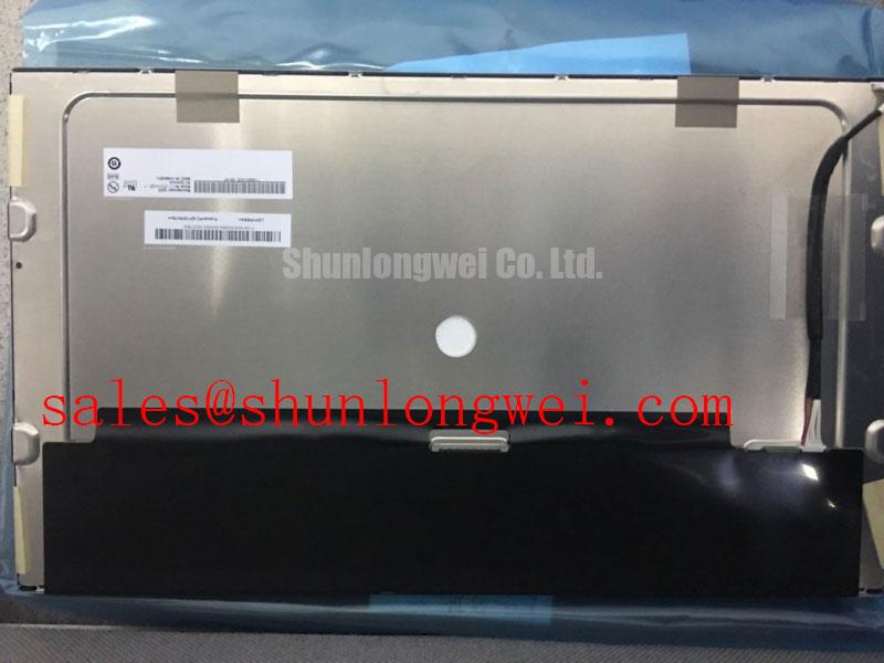
- Match the M185XW01 VF label and revision against the removed display before connecting the replacement cable.
- Inspect connector contacts, cable orientation, mounting points, and bezel clearance with the equipment isolated from power.
- Compare the controller configuration and backlight connection with the original assembly documentation before applying power.
- Record whether the reported defect changes with viewing angle, brightness adjustment, temperature, or displayed image.
The M185XW01 VF is an AUO TFT-LCD active matrix color display module. Replacement assessment should start with the complete assembly interface, not the model name alone: controller timing, mounting geometry, optical orientation, and illumination control must work together.
| Product identification | Baseline information |
|---|---|
| Model | M185XW01 VF |
| Manufacturer | AU Optronics (AUO) |
| Product category | LCD Display Panel |
| Module construction | TFT-LCD Active Matrix Color Display Module |
| Electrical, optical, and dimensional ratings | Consult the datasheet for the exact model and revision, supply requirements, interface, resolution, dimensions, viewing mode, surface treatment, and backlight specifications. |
Normally White TN Grayscale Inversion Mitigation & Optimal Viewing Direction Alignment
Display a grayscale ramp and inspect it from the intended operator position before fixing the panel orientation. As a Design Consideration, a normally white TN display can show substantial grayscale changes with viewing direction, including apparent inversion at unfavorable angles. This behavior is not confirmation that the M185XW01 VF uses that optical mode; the viewing assessment must follow the actual panel specification.
Compare dark gray separation, text edges, and warning colors above and below the display centerline. IPS and MVA viewing characteristics should not be treated as interchangeable with TN behavior, and a symmetric viewing cone is not an assumed specification. If enclosure orientation places the operator outside the useful viewing region, controller adjustments alone cannot correct the underlying angular response.
Under bright ambient illumination, evaluate reflected light with the complete protective window installed. Anti-glare treatment can spread reflections but can also alter perceived sharpness; anti-reflection treatment addresses a different optical mechanism. Neither treatment is established here as an M185XW01 VF feature. The AUO website provides manufacturer context for display assessment, rather than evidence of this revision’s optical ratings.
For a controller documented as using LVDS, an Engineering Recommendation is to check differential routing continuity, pair matching, connector transitions, and return paths against the transmitter and receiver requirements. Confirm the applicable JEIDA or VESA mapping before interpreting incorrect colors as panel damage. Evaluate image stability while nearby switching equipment operates; routing targets and timing margins belong to the complete interface design.
💡 Pro Tip: Keep differential pair routing balanced through connector transitions, then validate timing at the receiving interface rather than relying on trace length alone.
Suppressing Localized Thermal Gradients to Prevent Chronic Optical Yellowing (Color Shift)
Map the display enclosure temperature during brightness changes and thermal stabilization, paying particular attention to areas beside the illumination hardware and power electronics. As a Design Consideration, localized heating can contribute to brightness nonuniformity and color drift, but a yellow region does not identify a particular internal material or establish permanent optical damage.
If temperature mapping shows concentrated edge heating, assess a chassis heat spreading path that avoids loading the display frame. Any aluminum rail dimensions should follow measured heat flow, available attachment surfaces, electrical clearances, and enclosure constraints. Broadening heat distribution is useful only when the resulting assembly also respects panel mechanical and operating limits.
For an LED backlight implementation, assess constant current regulation and the documented dimming interface together. PWM behavior depends on driver response, illumination dynamics, camera exposure, and operator sensitivity; a generic frequency range does not establish flicker free operation. Check low brightness transitions for visible modulation, unstable output, and acoustic interaction with the installed electronics.
Backlight open circuit protection, short circuit response, and diagnostic outputs are driver properties that require circuit level confirmation. Where fault reporting exists, compare its timing with the enable command and illumination response. Record the test conditions instead of treating a protection event as proof that the panel is defective. Likewise, lumen maintenance metrics and statistical life claims require specified test conditions and supporting manufacturer data; they are not interchangeable with an assembly reliability rating.
Industrial Bezel Mechanical Envelope Tolerances & Mounting Screw Torque Optimization
Check the aperture, locating features, connector access, and mounting stack before tightening the display into its bezel. As a Design Consideration, the tolerance stack should prevent the housing, gasket, or protective window from applying uneven pressure to the display surface or frame. Compare the free assembly with the installed assembly using the same dark and midtone images.
Use the equipment drawing to establish fastener type, engagement depth, tightening sequence, and allowable torque. A screw size alone does not justify a torque value for this module. If the mounting arrangement supports progressive cross tightening, monitor image uniformity as clamping load increases; stop and inspect the stack when a new pressure dependent pattern appears.
During cross model assessment, treat LQ190E1LW42 as a comparison candidate, not a declared interchangeable replacement. Compare active area, outer dimensions, mounting features, resolution, timing, connector assignment, optical orientation, and illumination requirements before approving either mechanical or electrical compatibility.
When evaluating an AGV or forklift telematics display assembly, designers should also assess vibration restraint, harness movement, and readability from the installed operating position. A separate touch overlay introduces its own controller, grounding, optical bonding, and environmental requirements. Glove operation and wet surface response must be evaluated on that complete touch assembly, not inferred from the LCD model.
Single Vertical Hairline Defect & Sub-Pixel Column Driver Open-Circuit Localization
Display solid red, green, and blue fields in sequence and record whether the hairline stays at the same physical column. Follow with neutral gray and a contrasting pattern to distinguish persistent column behavior from content related artifacts. A stationary line can direct attention toward the panel signal path, but it does not independently prove an open circuit or a particular driver attachment failure.
As an Engineering Recommendation, compare the result with a verified controller configuration and compatible cable before assigning the defect to the module. Incorrect data mapping, connector contact problems, and signal integrity issues require different corrective actions. Avoid pressing the glass or flexing bonded connections to provoke a response.
For a dark screen, oblique external illumination can help reveal a faint image and separate image generation from illumination behavior. An absent visible image remains inconclusive without checking controller activity and the relevant power sequence. General transistor switching context is available in Amorphous Silicon (a-Si) TFT Technology; it does not establish the internal construction of this revision.
Use The Ultimate Guide to Industrial TFT LCD Technology for broader troubleshooting context. For the repair record, retain test images, controller settings, illumination state, and photographs under consistent ambient conditions. Evaluate sunlight readability with the installed window and actual surroundings rather than converting a dark room contrast rating into an unsupported outdoor performance claim.