Content last revised on September 22, 2026
Thermal Expansion Clearance Sizing across Heavy Industrial Metal Enclosure Cutouts
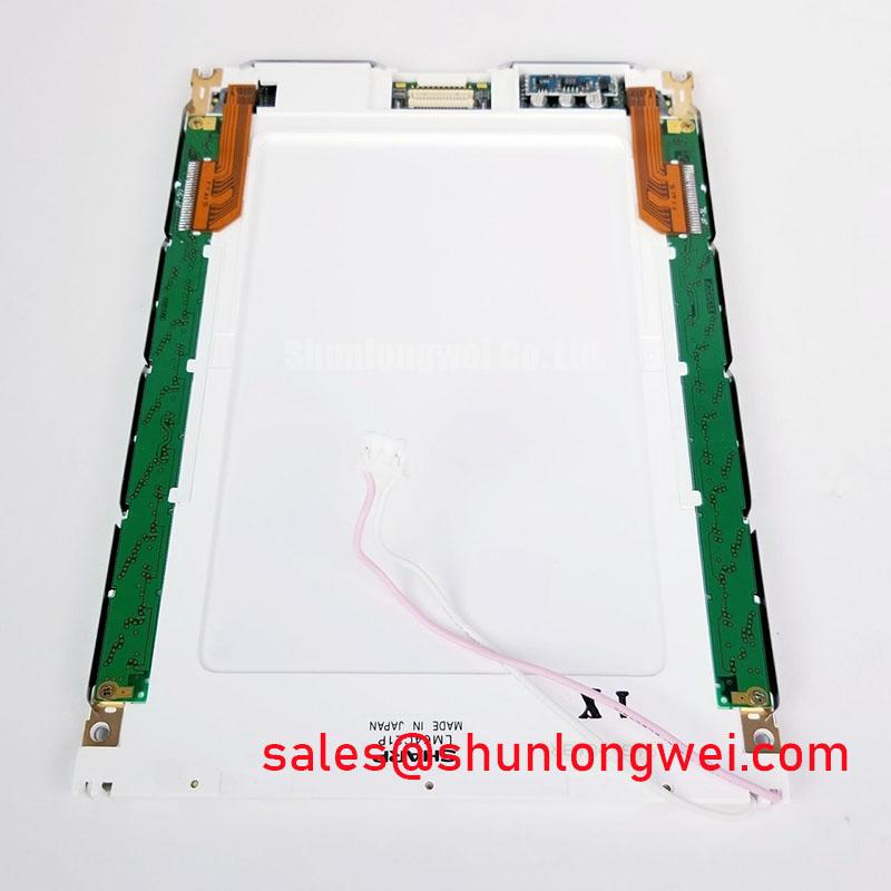
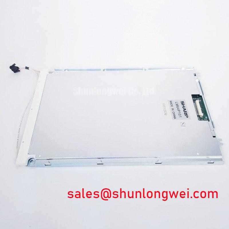
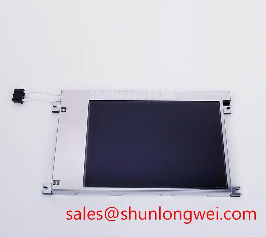
Begin incoming inspection of the LM64C031 by checking the TFT LCD display module face for edge pressure marks, panel cracks, connector damage, contamination, and nonuniform areas visible under a full white, black, red, green, and blue test image before it is installed in an industrial enclosure.
The LM64C031 is a Sharp TFT LCD display module. For maintenance work, the original machine documentation remains the required source for connector pinout, logic voltage, display timing, backlight arrangement, mounting geometry, and approved operating conditions.
| Model | LM64C031 |
| Manufacturer | Sharp |
| Product Category | TFT LCD Display Module |
| Module Construction | TFT LCD Display Module |
| Specification Status | Verify against original Sharp documentation |
Before placing the Sharp LM64C031 into a replacement bezel, inspect the enclosure cutout rather than assuming that the previous panel mounting condition was correct. A metal operator station, telematics housing, or machine mounted HMI can transmit force into the display perimeter when its fastening points are uneven, when the panel is clamped against a distorted opening, or when a gasket is thicker on one side than the other. These conditions can appear as localized bright areas, dark zones, edge shading, or optical mura after final assembly.
Use a flat reference surface to assess the enclosure opening and confirm that the visible area is not being used as a structural contact point. The system integrator should verify the original panel drawing and enclosure dimensions before defining clearance around the outer bezel. Clearance is a Design Consideration, not an LM64C031 factory dimensional requirement unless it is confirmed by the original Sharp documentation. The practical objective is to support the module at its specified mounting points while allowing the surrounding mechanical structure to expand and contract without concentrating load into the display face.
For assemblies using M3 hardware, a cross pattern tightening method can reduce uneven loading. A torque range of 0.35 to 0.45 N·m is a general industry mounting consideration for suitable M3 hardware and is not stated here as a Sharp module specification. The actual fastener selection, thread engagement, washer type, gasket stack, and final torque must be validated against the host enclosure design and the panel documentation.
💡 Bench Tip: Keep the display unpowered while inserting or removing its flexible cable, and confirm that the cable is fully parallel with the connector before closing the locking feature.
During optical incoming QA, illuminate the full panel with uniform test patterns and inspect from the normal operator viewing direction. A black image is useful for revealing unintended edge light and pressure related brightening, while white and gray patterns can reveal low contrast patches that are harder to identify on colorful application screens. Do not attribute every uneven region to the display itself. A temporary bench test outside the metal bezel helps separate panel behavior from enclosure induced stress.
Where the display is evaluated for heavy earthmoving equipment telematics or similar vibration exposed operator interfaces, the enclosure should be reviewed as a complete mechanical stack. This is an Engineering Recommendation: verify that cable routing, rear support, mounting surfaces, and service access do not place repeated bending or side load on the panel connector. The LM64C031 should be judged against the actual system vibration test plan and original equipment requirements rather than a generalized environmental assumption.
Logic Supply Sequencing and Driver Latch Up Checks
When a replacement display powers up with a blank image, unstable image, split content, or intermittent lines, first verify the host controller power sequence and signal configuration against the original LM64C031 documentation. The available product information identifies this product as a Sharp TFT LCD display module, but it does not establish a public logic supply value, rise time window, interface type, or data mapping in the information available here. The system integrator should verify the required supply voltage from the original panel documentation.
Logic sequencing matters because a panel controller and its source electronics should receive valid power and valid input conditions in the order required by the module manufacturer. A system that applies data before the necessary panel supply is stable, or that removes power while control signals remain active, can produce abnormal startup behavior. This is a Design Consideration; it is not a statement that the LM64C031 has a particular latch up limit or an approved sequence outside the original Sharp specification.
Check the repaired equipment with the display cable disconnected first, then compare host supply rails and enable timing with a known good equipment configuration when available. Inspect the connector for recessed contacts, partial latch engagement, and cable skew. A signal issue can resemble a panel defect, while a panel startup condition can resemble a controller fault. An oscilloscope comparison between the suspect machine and a known good signal path is more informative than assigning a cause from the visible symptom alone.
Where the host interface uses differential signaling, controlled impedance and pair length matching are system level concerns. A nominal 100 Ω differential routing target is a common interface design consideration in relevant differential display links, but it must not be treated as a confirmed LM64C031 interface requirement without the correct Sharp interface specification. The same applies to JEIDA or VESA mapping: either mapping must be confirmed from the original controller and panel documentation before any cable or logic board modification is made.
Service technicians should also check whether the replacement panel is being tested through an adapter board, converter, or extension cable. Such intermediary hardware can alter signal integrity, power sequencing, and enable behavior. For this reason, a direct connection using the approved machine harness is the preferred validation method after safe bench testing. Record the panel label, host controller revision, harness condition, and observed startup sequence so that repeat faults can be traced to the actual assembly condition.
Shielded FFC FPC Flat Flexible Cable Grounding across Connector Shells
The flexible display cable deserves the same inspection discipline as the screen itself. On a panel replacement, examine the cable along its full route for folded conductors, sharp bends, damaged stiffeners, contamination on exposed contacts, or a locking bar that is not fully seated. A cable can look connected while a small angular misalignment leaves one or more conductors with inconsistent contact pressure. The resulting display behavior may include intermittent pixel columns, moving noise, image dropouts, or a screen that responds differently when the enclosure is closed.
For equipment operating near motor drives, contactors, switched power supplies, and high current harnesses, cable shielding and grounding are host system design subjects. A shielded FFC, FPC, or differential display cable should be terminated according to the equipment design and connector construction. If the connector includes a conductive shell intended for shield bonding, the enclosure designer should confirm that the shield termination has broad, mechanically secure contact around the specified shell interface. This is an Engineering Recommendation for noise control, not an official LM64C031 connector specification.
A common mode ferrite may be evaluated when conducted or radiated interference is suspected, but selection must follow the measured noise spectrum, cable type, source impedance, and system compliance plan. Adding a ferrite without measurement can conceal the real issue or affect signal margins. Compare the panel image with the machine drives inactive and active, then inspect the waveform and grounding path before changing cable hardware.
In field repairs, avoid creating a tight cable bend at the connector exit. The bend radius and cable retention method should follow the cable supplier instructions and the equipment mechanical layout. Repeated flexing at a single point can reduce reliability over time, especially if the panel is mounted in a door, service hatch, or movable operator console. Secure the cable so that enclosure vibration is not transferred directly into the connector latch.
The The Ultimate Guide to Industrial TFT LCD Technology provides broader engineering context for evaluating panel integration, display interfaces, and common industrial LCD selection questions. For the LM64C031, those principles should always be applied only after the original panel documentation confirms the actual electrical and mechanical interface.
Where a repair requires cross model evaluation, the LM64P10 can be reviewed as a separate display product. It should not be assumed to be a drop in replacement. Connector arrangement, pin assignment, optical characteristics, mounting geometry, supply requirements, and timing compatibility must be checked independently before a substitution decision is made.
Backlight Drive Verification and Flicker Suppression in Industrial HMI Service
Backlight behavior should be evaluated separately from image data behavior. A panel with visible but very dim content under controlled illumination may point the technician toward the backlight drive path, while a uniformly dark panel can involve power, timing, enable, cable, controller, or panel conditions. These observations are diagnostic starting points only. The correct troubleshooting method is to verify the original system schematic, measure the relevant approved test points, and compare with a known good assembly where possible.
The available official information does not identify the LM64C031 backlight technology, backlight input voltage, current rating, dimming method, ignition requirements, or service life rating. It is therefore inappropriate to state that this model uses WLED or CCFL illumination, to assign a constant current value, or to claim a lifetime figure. The system integrator should verify the required backlight supply and control method from the original panel documentation before connecting a bench supply or replacement inverter.
For industrial display systems that use PWM controlled illumination, a frequency range of 200 Hz to 1 kHz is a general design consideration often reviewed when balancing visible flicker, camera interaction, acoustic effects, and dimming response. It is not an official LM64C031 requirement. PWM duty cycle behavior, dimming polarity, enable state, and allowable frequency must be validated at system level using the correct panel and backlight documentation.
A practical bench routine begins with visual inspection of the backlight connector and power path, followed by controlled testing through the approved host electronics. Check whether brightness changes consistently with the machine brightness command, whether image noise changes with dimming state, and whether intermittent behavior is affected by cable movement or enclosure closure. If the equipment includes a separate display controller or backlight driver, inspect it as part of the full signal chain rather than replacing the LCD module on the basis of brightness alone.
For systems that require a related industrial display solution or a separate assembly review, the LMS700KF01-001 is available for objective comparison. Its specifications, electrical interface, and mechanical fit must be evaluated independently and should not be treated as equivalent to the Sharp LM64C031 without documented verification.