Content last revised on October 22, 2026
Sharp LQ070T5BG01 Inspection and Service Checks
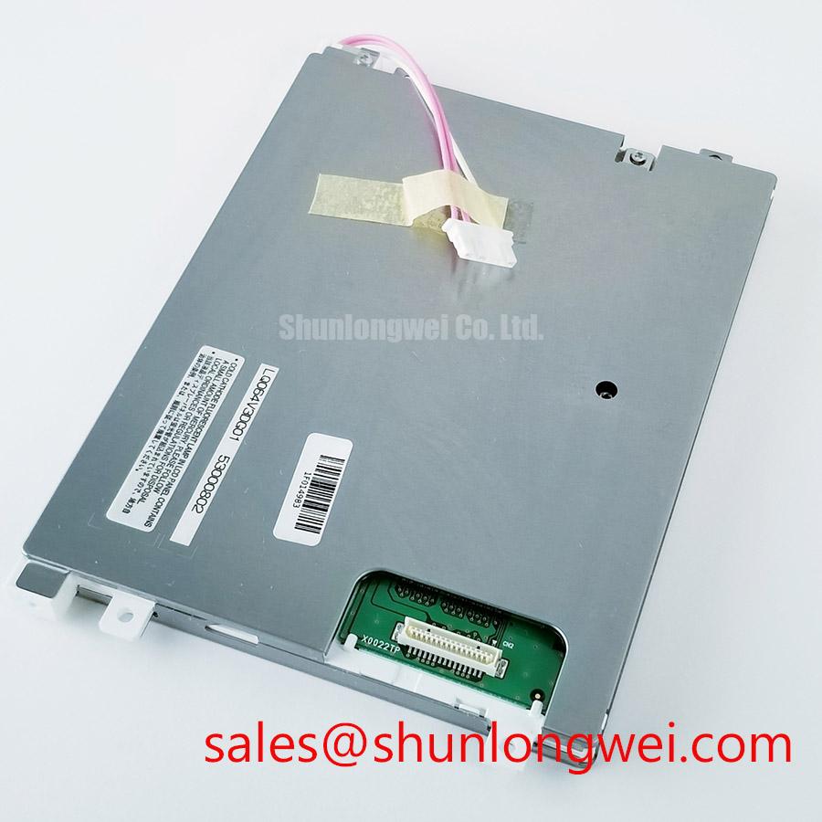
- Disconnect equipment power and inspect the LQ070T5BG01 label, connector orientation, and cable seating before reconnecting the display.
- Compare the controller’s configured panel profile with the original equipment schematic, including supply assignment and display timing.
- Separate a missing image from missing illumination by observing the screen under an external inspection light.
- Check mounting clearance and cable strain before tightening the display into its enclosure.
The Sharp LQ070T5BG01 is a TFT-LCD active matrix color display module for industrial display and HMI evaluation. For repair procurement, identify the complete model designation rather than relying on appearance or connector fit. The LQ070T5BG01 product page provides the model reference for matching the service requirement.
Specification checkpoint: Consult Datasheet for dimensions, resolution, interface, supply ratings, backlight construction, optical performance, temperature limits, and timing. The thermal, LED, optical-material, and mapping topics below are Design Considerations, not verified features or ratings of this model.
Field Alert: Disconnect panel and backlight power before reseating display cables to avoid applying signals through a partially engaged connector.
Mitigating Gray-to-Gray (GTG) Response Time Escalation during Cold-Start Machine Power-Up
Compare moving edges immediately after startup with the same pattern after the display reaches a stable temperature. As a Design Consideration, liquid-crystal response generally slows when temperature falls; this can produce trailing or sluggish gray transitions without indicating a defective signal cable. Keep the source pattern, brightness setting, and controller configuration unchanged during the comparison.
Distinguish this optical response from delayed controller initialization. A moving object that leaves a persistent trail suggests a different investigation from an image that appears late but then updates normally. Record panel-surface temperature alongside image behavior, and restrict environmental testing to the documented operating envelope. An industrial label does not establish permission for subzero operation or a particular thermal-cycle range.
At the controller interface, evaluate clock stability and data setup and hold against the applicable transmitter and panel timing requirements. Engineering Recommendation: capture startup behavior as well as steady operation, because an apparently stable image can conceal marginal initialization timing. Probe loading and measurement reference placement must preserve the signal being assessed.
Inspect the accessible perimeter for separation, moisture traces, or mechanical stress without disturbing the panel seal. Do not infer sealant chemistry or cycle endurance from appearance. The Sharp Devices Europe Industrial Display Solutions website provides manufacturer context for display technologies; qualification decisions still require documentation applicable to the exact panel.
Backlight Thermal Dissipation & Optical Stack Preservation
Map an uneven bright or dark region against the enclosure contact points before changing the backlight drive setting. Mechanical pressure, illumination distribution, contamination, and drive instability can produce overlapping symptoms. Compare the screen with its mounting load released only where the equipment service procedure permits, keeping electrical connections undisturbed.
For an LED-equipped display assembly, Design Consideration: assess the thermal path from the illumination hardware into the supporting structure. Heat-spreader geometry should follow measured dissipation, available contact area, and enclosure temperature, rather than a generic rail dimension. Avoid adding clamping force that distorts the display stack. Neither PMMA construction nor an edge-lit architecture should be attributed to this model without a matching assembly specification.
At the backlight controller, examine enable, dimming, current regulation, and any documented fault output together. An open load can provoke protective shutdown, while a shorted load can trigger a different protection response; interpret both through the driver’s own documentation. Capture the startup sequence rather than treating a low steady-state output as proof of a failed power supply.
Engineering Recommendation: evaluate dimming for visible modulation and camera interaction across the equipment’s intended brightness range. PWM frequency alone does not establish flicker-free performance. Likewise, assess ambient reflections on the actual front surface rather than assuming an anti-glare or anti-reflection treatment. Broader enclosure and thermal considerations are covered in Industrial Display & HMI Solutions; those system considerations do not establish panel-specific lifetime ratings.
Single Vertical Hairline Defect & Sub-Pixel Column Driver Open-Circuit Localization
Display solid red, green, and blue fields in sequence, then compare whether the vertical defect stays at the same screen coordinate. Follow with a neutral image to distinguish a consistently missing color contribution from a content-dependent artifact. Record the result photographically before disturbing connectors, so subsequent changes can be compared against a repeatable baseline.
A stationary line can involve the panel’s column-addressing path, but it does not by itself prove an internal driver fracture. Cable faults, controller output errors, and panel electronics deserve separate checks. Engineering Recommendation: compare the source with a known-good compatible display or approved test fixture where available, changing only one element at a time. Avoid pressing the bezel or flexing the panel to provoke a response.
For a dark screen, direct an inspection light obliquely across the surface while the controller displays a known pattern. A faint recognizable image supports investigating the illumination path, but does not identify the failed part. Check the relevant supply, enable state, connector condition, and driver fault behavior before assigning responsibility to the panel.
Brightness maintenance and failure statistics answer different questions. L70/B50 terminology is not interchangeable with MTBF, and neither establishes an operating-life promise for this module. When comparing service materials, treat Sharp LQ057Q3DC03 as a separate candidate requiring a full mechanical, electrical, and optical comparison—not a drop-in replacement established by brand or naming similarity.
VESA vs. JEIDA Data Mapping Alignment & Even/Odd Channel Signal Integrity
Match the controller output assignment to the panel connector definition before changing a mapping option. Where an interface uses VESA or JEIDA mapping, an incorrect assignment can distort color significance even when synchronization remains stable. Establish the actual interface first; these mapping conventions are not universal TFT-LCD requirements.
Engineering Recommendation: compare channel allocation, pixel ordering, clock relationship, and data-valid timing against the approved equipment configuration. Split images or alternating-column artifacts can involve channel assignment, timing, or physical connectivity. Use diagnostic patterns to distinguish these possibilities rather than interpreting every divided image as a mapping fault.
For a differential interface, preserve the specified transmission environment through the cable and connector transition. Evaluate pair skew, discontinuities, and common-mode behavior using the interface requirements and actual receiver conditions. Measure supply rise, signal arrival, reset, and illumination enable together to establish whether startup sequencing follows the equipment specification.
When evaluating integration into an ultrasound diagnostic display or surgical-navigation terminal, the equipment owner should assess image performance, electrical compatibility, and applicable system requirements independently. For the repair handoff, retain the validated controller profile, connector assignment, startup captures, and pattern-test results so the replacement decision rests on reproducible evidence.