Content last revised on November 6, 2026
Shielded FFC/FPC Flat Flexible Cable Grounding across 360-Degree Connector Shells
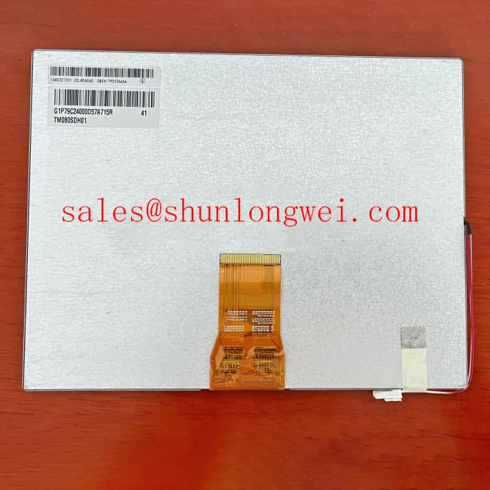
I first display a stationary grayscale pattern and compare image stability with nearby switching equipment idle and operating. For the TM080SDH01-00, this separates repeatable pixel defects from interference that changes with equipment activity. I then use full-screen black, white, red, green and blue patterns to record suspect pixel locations. A defect that remains at the same coordinates deserves a different investigation from a moving horizontal band.
Design Consideration: Where the equipment harness includes shielding and a conductive connector shell, inspect the shield termination around the connector perimeter rather than assuming a drain wire provides equivalent high-frequency continuity. Check the enclosure bonding path and cable routing against the equipment drawing. Shield construction belongs to the harness design; it is not an established feature of this Tianma module.
A common-mode ferrite is a system-level suppression option only after measurements identify a relevant interference path. Compare image behavior and signal quality before and after any harness change. On an interface using differential signaling, inspect the waveform at the receiving end with appropriate probing; a clean transmitter waveform alone does not establish adequate receiver margin.
💡 Bench Tip: With power removed and ESD protection in place, insert the flat cable squarely to its seating reference before closing the connector latch.
For equipment with PWM backlight control, compare commanded brightness with measured luminance throughout the usable adjustment range. Check low-brightness behavior for unstable illumination, visible modulation and audible driver noise. Select the operating frequency and duty-cycle limits from the actual driver requirements and system validation rather than assigning a generic dimming range to the panel.
Preventing Frame Lag & Image Smearing in Cryogenic Storage & Outdoor Industrial Facilities
Record moving edges and gray transitions at stabilized panel temperatures before treating cold image smearing as a cable fault. Design Consideration: Liquid crystal response generally slows as temperature falls, so a static test pattern can look acceptable while moving text leaves visible trails. Compare the same transitions, frame settings and observation conditions across the equipment’s approved temperature range.
Separate response time from controller latency. Delayed arrival of a complete frame points toward the video path or processing chain, whereas a slow optical transition requires luminance measurement against the electrical image command. Any response compensation should be assessed for overshoot and tonal errors as well as apparent motion improvement. Chamber conditions must remain within the documented module limits.
For optical inspection, measure brightness and white-point consistency at repeatable screen positions after stabilization. Keep ambient illumination and viewing geometry consistent between measurements. Edge darkening, localized tint and pressure-sensitive patches should be documented separately because they can have different optical, electrical or mounting contributors. Apply the purchase specification’s acceptance criteria rather than inventing a universal pixel or uniformity limit.
Inspect mounting clearance, cable strain and bezel contact after thermal exposure. Expansion differences can transfer stress into the display assembly, particularly when the enclosure constrains its edges. Surface treatments also require identification: anti-glare and anti-reflection treatments affect reflections differently, and neither should be attributed to this model without its optical specification. The manufacturer’s Tianma NLT Industrial TFT-LCD Display Technologies information provides useful context for distinguishing display technology and optical options.
When assessing environmental margins, use Industrial Display & HMI Solutions as supporting integration guidance alongside the equipment requirements. Backlight lumen maintenance and MTBF describe different reliability measures; neither establishes a service-life guarantee for this module.
High-Voltage Striking Potential & Secondary Coil Insulation Testing
Identify the installed backlight power circuit from the equipment schematic before selecting a probe or insulation test method. Design Consideration: High-voltage striking and secondary winding checks apply to a documented lamp inverter circuit. They do not establish the backlight architecture or permissible test voltage of the TM080SDH01-00.
For a documented constant-current LED driver, compare the enable command, current regulation and protection status during startup and dimming. An illuminated status indicator does not prove that the backlight current path is complete. Conversely, a protection shutdown requires checking the load connection, wiring and driver behavior together before assigning the fault to the display assembly.
Open-load and short-circuit responses are driver-specific. Review the actual protection thresholds and fault-output definitions, then observe whether the driver latches off, retries or requires a reset. Measurements should distinguish a disconnected load from a supply collapse or control interruption. Keep insulation qualification separate from routine functional testing, with test boundaries defined by the equipment’s approved procedure.
Assess driver efficiency using measured input power and delivered electrical load under defined conditions. Assess optical output separately with a luminance instrument. Falling brightness can involve temperature, drive current or optical aging; brightness alone cannot establish the cause. Likewise, acoustic noise should be correlated with switching operation and mechanical mounting before changing the dimming command.
Logic Supply Voltage Sequencing to Reduce Driver IC Latch-Up Risks
Capture the panel supply, image-interface activity and backlight-enable signal on the same startup and shutdown record. Design Consideration: Compare their order and transition behavior with the panel timing specification, including whether signal lines remain active while the receiving circuitry is unpowered. Repeat the capture during equipment restart and supply interruption, where sequencing can differ from a normal cold start.
Match the controller output to the documented interface, connector orientation and pin assignment. Where differential transmission is specified, evaluate the cable and termination as a complete channel. Where a parallel interface is specified, evaluate clock-to-data timing at the receiver. Clock jitter, setup time and hold time need comparison with the applicable receiver limits across the approved operating conditions.
Data mapping also belongs in the compatibility check. On an interface that specifies JEIDA or VESA mapping, compare the controller configuration with the panel definition before interpreting incorrect colors as damaged pixels. Use fine text, color ramps and alternating patterns to distinguish mapping, timing and image-scaling problems.
For replacement evaluation, compare TCG070WVLPCANN-AN00 against the required dimensions, active area, resolution, interface, power and optical behavior; a product link does not establish direct interchangeability. Railway passenger information terminals and cab signalling displays are potential compatibility assessments, subject to equipment-level qualification. The Tianma Microelectronics Industrial TFT Displays resource can support product-family identification, while the exact module drawing and timing specification determine the final electrical and mechanical match.