Content last revised on November 6, 2026
TM080SDH01-41 Identification and Initial Checks
- Inspect the panel surface and bezel for pressure marks, edge damage, contamination, or evidence of uneven clamping.
- Compare the installed panel’s connector position, cable orientation, and mounting points with the replacement assembly.
- Run red, green, and blue test fields to distinguish visible pixel-line behavior from uneven illumination.
- Check the controller documentation for the required supply, signal interface, and image-data mapping before connecting the panel.
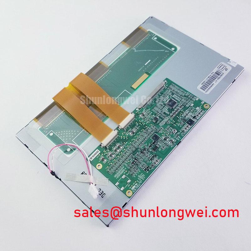
Before replacing a display in a CNC operator panel or robot teach pendant, record the original panel orientation and inspect the flex connection for creasing or a partially released lock. The product identification fields specify Manufacturer: Tianma and Part Number: TM080SDH01-41. The form factor is a TFT-LCD active-matrix color display module. Verify the diagonal size, resolution, and interface in the panel-specific documentation; generic descriptions such as “Standard Industrial Resolution” and “Industrial Standard Interface” do not establish those specifications. These identification fields do not establish a connector pinout, timing table, or mechanical drawing.
| Manufacturer | Tianma |
| Part Number | TM080SDH01-41 |
| Product Category | TFT-LCD Display Module |
Mechanical Stress Checks at the Panel and Interconnect
Assess mechanical strain before investigating image artifacts: a panel that is twisted by its frame or pressed unevenly can show symptoms that change as the assembly is handled. Confirm that the enclosure supports the panel along its intended mounting areas, and check that fasteners do not pull the bezel into a bowed shape. Compare the opening, mounting features, and connector clearance with the equipment drawing rather than relying on the visible glass dimensions alone.
For a bench check, display solid red, green, and blue fields in succession and note whether a line, patch, or dark region remains fixed in the same location. Then direct a flashlight obliquely across the screen while the image is active. A faint image visible under external illumination can help separate an illumination-path concern from a pixel or driver-related artifact, but it does not identify a failed component on its own. Record the result with the panel in its normal orientation and again after reseating the assembly without applying pressure to the active area.
Flex circuits and their connectors need strain relief that suits the equipment’s actual movement and service access. Avoid sharp folds, repeated flexing at the connector exit, and routing that allows a cover to press on the cable. In cold environments, liquid-crystal response may become slower; evaluate transition behavior only within the documented operating conditions for the panel and complete assembly. A heater or other temperature-control measure is a system-level choice, not an assumed feature of this model.
Logic-Supply Sequencing and Interface Verification
Resolve the electrical interface from the panel documentation and controller schematic before applying power. “Industrial Standard Interface” is a category-level description, not a pin assignment: it does not establish whether the connection is LVDS, TTL, or another format. Check connector pin numbering, signal direction, ground references, supply requirements, and any enable or backlight-control signals against the applicable documentation. A connector that mates mechanically can still have a different pinout.
Review the startup and shutdown sequence as a complete path from controller to display. Confirm that the supply reaches its permitted range and that control and image signals follow the panel’s specified timing. During troubleshooting, capture the sequence at the panel connector and compare it with a known-good system record. A white screen, a blank image, or residual image during shutdown can have several causes, including sequencing, signal integrity, or the controller’s display state; treat the symptom as a prompt for measurement rather than a one-to-one diagnosis.
If LVDS is confirmed, verify that the controller’s data mapping matches the panel requirement. JEIDA and VESA mappings are not interchangeable assumptions, and a mismatch can produce incorrect colors. Design Consideration: Keep confirmed differential pairs closely coupled with consistent routing and minimal stubs, then validate signal quality at the receiving connector under the system’s operating conditions.
When comparing another display option, use TM097TDH01-00 as a separate reference point, not as proof of drop-in compatibility. Compare the active area, outline, mounting, connector, signal format, timing, and optical requirements before selecting a replacement. For display-side system context, G084SN03-V4 is another reference; its presence does not establish that it is a compatible driver or companion for this panel.
Emissions Evaluation Around Switching Equipment
When image jitter or horizontal bands appear near switching equipment, trace the signal path and return path before changing panel settings. Keep display cables away from high-current motor wiring where the enclosure layout permits, avoid unnecessary cable loops, and maintain a clear, deliberate bond between cable shielding and the chassis. The appropriate shield termination depends on the equipment’s grounding architecture, connector construction, and safety requirements; a display module alone cannot establish system EMC compliance.
Inspect the flex or display cable for incomplete seating, damaged contacts, and routing against noisy power conductors. If the design uses a shielded cable, verify that the shield makes the intended contact at the enclosure entry rather than ending in a long, unbonded pigtail. Common-mode filtering may be evaluated as a system design measure when measurements indicate a conducted or radiated interference path, but ferrite selection and placement should follow test results rather than guesswork.
For a repeatable comparison, keep the displayed test pattern and equipment state consistent while checking the image with the motor drive inactive and active. Use an oscilloscope or other suitable instrumentation to examine the relevant signals and compare the result at the controller and panel ends. A display issue that correlates with drive operation is useful diagnostic evidence, but it does not by itself demonstrate a standards failure or identify a single source. Record cable position, shield contact, chassis bonds, and test conditions so that any change can be evaluated on the same basis.
Image Stability, Contrast, and Temperature Evaluation
Evaluate image quality at the viewing position used by the operator, including normal viewing angles and the ambient lighting expected at the machine. The panel’s technology, viewing-angle specification, contrast figures, and surface treatment are not established by the baseline identification fields, so do not infer TN, IPS, MVA, anti-glare etching, or a particular contrast ratio from the model description alone. Compare photographs or direct observations under consistent brightness and test-pattern conditions when assessing a candidate replacement.
Long-running HMI screens often contain fixed labels and status regions. Where the equipment permits, use sensible screen-state management, avoid unnecessary maximum illumination, and monitor for persistent image retention during extended operation. These are system-level operating practices, not a specified endurance rating for this part. Likewise, do not assume optical bonding, a sealed front surface, or a particular ingress-protection level; the enclosure, cover lens, adhesive system, and assembly process determine those characteristics.
Temperature evaluation should cover the panel’s documented operating range and the actual thermal conditions inside the enclosure. Check for changes in transition appearance, flicker, or uneven illumination after the assembly reaches its operating state, and distinguish panel behavior from controller timing or supply variation. For additional background on TFT-LCD operation and practical evaluation, see Microscopic Analysis of TFT LCDs. Use the panel-specific documentation and measured system behavior to guide integration decisions.