Content last revised on October 15, 2026
Tianma TM097TDH01-00 Incoming Inspection and Bench Preparation
- Match the TM097TDH01-00 label and revision to the equipment service record before connecting the display harness.
- Inspect connector contacts, cable alignment, locking features, and mounting surfaces under magnification before applying power.
- Prepare full-screen black, white, red, green, blue, and grayscale patterns for pixel inspection and uniformity checks.
- Record the existing controller configuration and backlight connections so that bench results can be compared with the original installation.
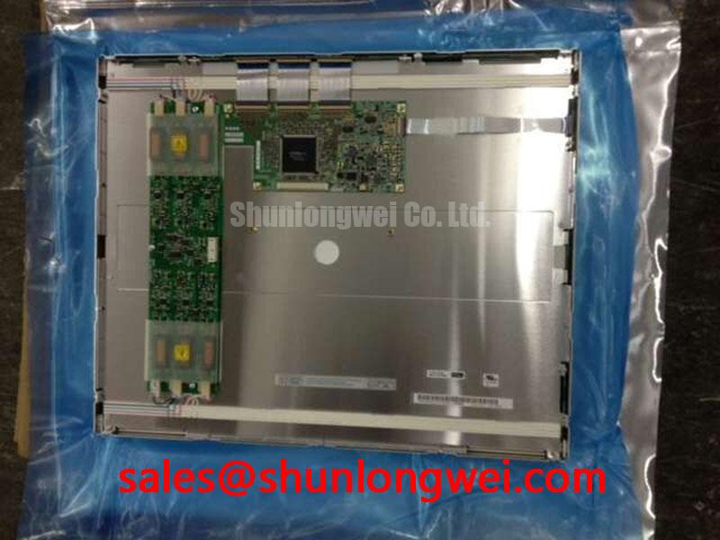
The Tianma TM097TDH01-00 is a TFT-LCD active matrix color display module for industrial LCD/HMI evaluation. Incoming inspection should establish connector condition, stable image reproduction, and optical consistency before installation. These observations help separate panel behavior from controller configuration, harness faults, and enclosure effects.
| Product identification | Specification or verification requirement |
|---|---|
| Model | TM097TDH01-00 |
| Manufacturer | Tianma |
| Product category | TFT-LCD display module |
| Module construction | TFT-LCD active matrix color display module |
| Electrical, optical, and mechanical ratings | Consult Datasheet for resolution, dimensions, supply voltage, interface, backlight configuration, temperature limits, and viewing-angle ratings. |
💡 Bench Tip: With power disconnected and ESD protection in place, seat the display cable squarely before closing its connector lock.
Industrial EMI Noise Immunity, Chassis Shielding Continuity & Common-Mode Ferrite Chokes
Compare pixel jitter and horizontal noise bands with nearby drive equipment stopped and running while keeping the displayed pattern unchanged. As a Design Consideration, correlation with drive activity helps identify an interference path, but does not establish whether the disturbance enters through the display supply, signal harness, or chassis connection. Record the operating condition alongside each observation.
Inspect shield terminations wherever the equipment drawing specifies a shielded display harness. A continuous enclosure connection can reduce interference coupling; a damaged termination or poorly seated connector can interrupt that path. Full circumferential shield bonding applies to suitable shielded cable assemblies and connectors. It should not be assumed to exist on an ordinary flat flexible cable.
As an Engineering Recommendation, evaluate a common-mode ferrite only after identifying the affected cable and frequency range. Its suitability depends on the harness construction, noise spectrum, and resulting signal quality. Compare the displayed image and receiver waveforms before and after the change, using probing methods that minimize disturbance to the circuit. Ferrite installation alone does not establish equipment EMC compliance.
If artifacts change after the assembly warms, distinguish electrical interference from temperature-dependent optical response. Liquid-crystal transitions can slow as temperature falls, making moving edges appear smeared even when static patterns remain stable. Evaluate this behavior within the specified operating range. Any enclosure heating should follow the equipment thermal design and be checked for temperature uniformity across the display.
Backlight Identification and Illumination Diagnostics
Identify the installed backlight circuit from the equipment schematic before interpreting a dark image or attempting driver measurements. The CCFL inverter terminology in this section describes a system diagnostic category, not a confirmed backlight specification for the TM097TDH01-00. Apply the relevant procedure to the documented assembly.
As a Design Consideration, first establish whether image data is present while illumination is absent. A faint image visible under external light can help direct investigation toward the illumination path, although it does not isolate the failed part. Check driver enable behavior, connector seating, and supply stability against the equipment service information before exchanging assemblies.
For a documented CCFL installation, ignition testing requires appropriately rated measurement equipment and the inverter manufacturer's procedure. For a documented constant-current backlight installation, examine enable and dimming behavior together with the driver output. Audible buzz should be correlated with brightness setting and operating state rather than treated as proof of a particular electrical fault.
Assess illumination uniformity after the assembly reaches a repeatable thermal condition. Keep the image, brightness command, measurement positions, and viewing geometry consistent. Record localized bright regions, dark corners, and color differences separately. As an Engineering Recommendation, compare these observations before and after mounting to identify enclosure pressure or restricted heat removal. Backlight service-life claims require the manufacturer's stated conditions; half-brightness life and MTBF describe different quantities.
VESA vs. JEIDA Data Mapping Alignment & Even/Odd Channel Signal Integrity
Match the controller output configuration to the panel interface definition before interpreting incorrect colors, missing grayscale steps, or divided images. As a Design Consideration, VESA and JEIDA mapping checks apply to interfaces that specify those conventions. Even/odd channel assignment likewise applies only where the documented architecture uses separate pixel channels.
Compare connector orientation, signal names, channel order, and cable continuity with the equipment drawing. A mechanically fitting connector does not establish electrical compatibility. During repair planning, TX18D216VM0BAA can be included in a separate specification comparison, but interchangeability requires matching the mechanical envelope, interface, timing, power requirements, and optical performance. Model names alone provide no compatibility evidence.
As an Engineering Recommendation, inspect clock and data at the receiver under the controller's intended operating conditions. Evaluate differential routing against the interface impedance requirement, and assess jitter and setup/hold margins against the applicable timing specification. TTL signaling uses a different electrical approach from LVDS; differential-pair rules should not be transferred to TTL connections. Cable extensions and adapters also require evaluation because they change the signal path.
Use a grayscale ramp to distinguish data-format problems from tonal-response problems. Missing levels, contouring, or color casts can involve mapping, controller processing, or the display drive path. Where accessible service information permits, compare timing-controller reference and gamma voltages with the specified values using a suitable probe. Adjusting gamma settings to conceal intermittent data corruption can obscure the original fault.
Viewing-Angle Evaluation for Multi-Angle Consoles
Observe the same grayscale and color patterns from the center and from the actual operator positions before judging console readability. IPS, MVA, and TN describe different liquid-crystal approaches; they are comparison terms here rather than confirmed technology assignments for this model. Viewing-angle acceptance should use the panel's specified measurement criterion and the equipment's intended observation geometry.
As a Design Consideration, separate angular color shift from reflections and backlight nonuniformity. Repeat observations under controlled ambient light, then introduce representative external illumination without changing the image settings. Evaluate any cover window and documented anti-glare treatment as part of the assembled optical path. A surface treatment can alter reflection behavior without establishing outdoor readability by itself.
When evaluating compatibility with a marine radar or navigation bridge console, designers should assess sunlight exposure, enclosure sealing, condensation control, and readable grayscale at the installed viewing position. The Industrial Display & HMI Solutions reference provides broader integration context. Tianma NLT Industrial TFT-LCD Display Technologies provides manufacturer-level context for industrial display and optical technology.
Finish the optical acceptance check with the module secured in its intended mounting arrangement. Compare the mounted image with the bench image for pressure-related shading, edge discoloration, and changes in uniformity. Record pixel defects by location and test pattern, then evaluate them against the agreed acceptance specification. Keep the approved controller settings and measurement conditions with the inspection record so that subsequent replacements can be assessed consistently.