Content last revised on October 12, 2026
G084SN03-V4 Identification and Replacement Inspection
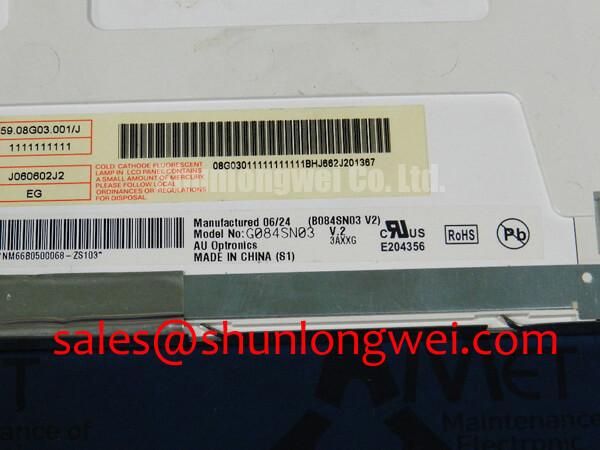
- Confirm the installed panel marking and compare the connector keying before removal.
- Inspect the FPC bend path, latch engagement, bezel seating, and signs of uneven chassis pressure.
- Record the ambient temperature and display response during cold start, especially in an enclosed cabinet.
- Check the backlight driver isolation and cable routing before applying power to a replacement panel.
| Product identification | Information |
|---|---|
| Model | G084SN03-V4 |
| Manufacturer | AUO |
| Product category | Industrial LCD panel |
| Display construction | TFT-LCD active matrix color display module |
| Specification verification | Consult the applicable AUO specification and mechanical drawing before installation. |
The G084SN03-V4 is an AUO TFT-LCD active matrix color display module intended for evaluation as an industrial HMI or equipment display replacement. Mechanical dimensions, interface voltage, timing, optical ratings, backlight configuration, and connector assignments must be matched with the original panel documentation before installation. This distinction matters when a display is being fitted into a railway passenger information system, cab signalling display, industrial operator console, or control cabinet. These applications also require system-level qualification; panel compatibility alone does not establish suitability.
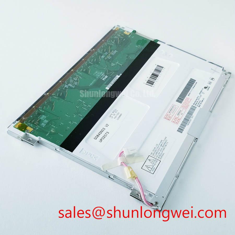
When removing the existing display, support the panel by its rigid perimeter rather than pulling on the flexible cable. A partially released connector latch can leave the display apparently installed while causing intermittent image data, backlight behavior, or touch interface faults if a separate touch assembly is fitted. The replacement should be compared with the removed unit for connector position, cable exit direction, mounting-hole alignment, viewing orientation, and clearance around the bezel.
Polarizer Durability and Optical Retardation Film Inspection under Direct Industrial Lighting
Direct industrial lighting makes polarizer condition and surface treatment immediately relevant to display acceptance. Inspect the front optical surface under a controlled light source and compare it with a known-good screen at identical viewing angles. Look for pressure marks, circular cleaning traces, edge lifting, scratches, localized haze, and changes in surface reflection. These symptoms should be recorded as optical observations rather than assigned to a single internal cause.
LCD viewing behavior depends on the panel optical stack and its viewing-angle characteristics. A useful reference for the general relationship between viewing angle and contrast perception is the industry discussion of Viewing Angle Characteristics in LCDs. The inspection should cover the operator’s actual eye position, not only a centered laboratory position. A display that appears acceptable directly in front of the panel may show grayscale inversion, contrast loss, or color shift when viewed from a cab-side angle.
TN, IPS, and MVA technologies do not present identical viewing behavior. TN-type grayscale inversion can become more visible above or below the normal viewing axis, while IPS and MVA structures are commonly evaluated for wider and more symmetrical viewing performance. The frequently quoted 85°/85°/85°/85° viewing-angle pattern must not be assigned to the G084SN03-V4 without a matching AUO specification sheet. Treat such values as a comparison target only when reviewing an optical replacement.
Anti-glare treatment also requires practical checking. Under strong overhead illumination, observe whether reflected lamps or sunlight obscure status text, warning colors, or low-contrast graphics. Surface etching can reduce mirror-like reflections, but aggressive cleaning, abrasive cloths, or solvent exposure may change the surface appearance. Use a clean, soft material and a cleaning method approved for the installed display assembly. Do not press the center of the panel while wiping because mechanical pressure can create temporary or persistent optical non-uniformity.
Cold operation changes the perceived response of liquid crystal material. At sub-zero temperatures such as −20°C to −30°C, gray-to-gray transitions can become visibly slower, producing trailing on moving symbols or delayed updates on a passenger information screen. These temperatures are general examples, not confirmed operating limits for the G084SN03-V4; keep testing within the panel’s documented limits. A cold-start evaluation should separate the time required for the host system to boot from the time required for the panel image to reach stable visual performance. If the equipment uses a cabinet heater or controlled warm-up strategy, the system engineer should verify its temperature sensing, activation logic, and physical separation from the LCD surface.
Optical retardation films and polarizers should be inspected for color changes that appear only at oblique angles. Such changes can arise from viewing geometry, polarization interaction, pressure, or thermal history. Compare the same test image from several practical operator positions and document the result with consistent camera exposure. The general structure of polarizers and optical glass is described in this LCD polarizer and optical glass reference, but the G084SN03-V4 assembly should be judged against its own approved optical requirements.
High-Voltage Striking Potential and Secondary Coil Insulation Testing
Backlight identification must come before any electrical substitution. A legacy LCD assembly may use a high-voltage CCFL inverter, while another assembly may use an LED driver with a different current-control and dimming arrangement. The presence of a similar connector does not establish electrical compatibility. The integrator should verify the backlight type, supply requirements, enable signal, dimming method, and insulation arrangement from the original panel and driver documentation.
For CCFL equipment, cold ignition can involve a striking potential in the approximate 1500 to 1650 Vrms range in some inverter designs. This range is a design reference for the associated inverter and lamp circuit, not a confirmed rating of the G084SN03-V4 unless it appears in the applicable manufacturer documentation. Use a properly rated high-voltage probe and follow the test instrument manufacturer’s connection procedure. Inspect the secondary coil, lamp cable, connector body, and nearby grounded metalwork for contamination, tracking, cracked insulation, or carbonized surfaces with power removed and stored energy safely discharged.
Secondary insulation testing should be performed with the display disconnected from sensitive logic and only under a documented test method. The applied test level, dwell time, leakage interpretation, and allowable discharge procedure belong to the equipment safety plan. An insulation result should be interpreted alongside visible damage, inverter behavior, and cable routing. A high-voltage test performed across an unsuitable interface can damage the panel or produce an invalid result.
LED backlight systems require a different approach. A constant-current driver may use PWM dimming, and a control specification may describe a wide dimming ratio such as 1000:1. That ratio must be treated as a driver-level parameter unless confirmed for the complete G084SN03-V4 assembly. Check whether the host controller supplies brightness commands, an enable signal, or a dedicated driver interface. Do not connect a CCFL inverter to an LED input or apply an LED current source to a CCFL assembly.
Acoustic buzz should be investigated at the driver, transformer, mounting bracket, and cable interface rather than attributed automatically to the LCD. Record whether the sound changes with brightness, temperature, refresh activity, or cabinet vibration. These observations help distinguish electrical excitation from mechanical resonance. Any replacement driver should be evaluated for its own switching behavior, thermal dissipation, and electromagnetic interaction with the display signal path.
Claims involving a half-life exceeding 50,000 hours or a specific MTBF require a product-level reliability source and defined operating conditions. They should not be transferred from a generic LED specification to this AUO display module. For maintenance planning, use the actual backlight type, brightness setting, cabinet temperature, operating schedule, and ventilation condition recorded by the equipment owner.
Industrial Bezel Mechanical Envelope Tolerances and Mounting Screw Torque Optimization
Mechanical alignment is the first control against bezel stress and localized optical non-uniformity. Place the panel on a clean, supported surface and confirm that the chassis does not contact the active area, polarizer edge, connector, or flexible cable. The outer bezel envelope, mounting-hole pattern, and clearance must be taken from the original assembly drawing or a direct dimensional comparison. A visual match alone is insufficient when the surrounding metalwork has limited tolerance.
Use a cross-pattern fastening sequence so the bezel settles progressively rather than loading one corner first. A general design consideration for small M3 display fasteners, where specified for the assembly, is a light, controlled tightening approach, with the final torque determined by the chassis material, washer arrangement, thread engagement, and panel manufacturer’s mechanical specification. Do not treat a generic fastener torque as an AUO factory requirement.
Maintenance Note: Tighten display fasteners evenly and inspect the gasket or sealing strip during scheduled service because compression at one edge can create leakage paths, optical pressure marks, or cabinet vibration transfer.
After fastening, display a dark field and a mid-gray field before fitting the front cover. Observe the corners, edge zones, and areas near each screw. Localized brightening, darkening, or cloudy patches can indicate mechanical loading, uneven support, contamination, or optical stack disturbance. Loosen and re-seat the assembly only after power is removed and the panel has been protected from dust.
Direct sunlight also changes the acceptance condition. A contrast target such as 500:1 at 50,000 lux belongs to a defined optical test method and must not be declared as a confirmed G084SN03-V4 rating without supporting data. In practical equipment evaluation, compare critical symbols and alarm colors under the actual enclosure window, viewing direction, and ambient reflections. An anti-glare surface can improve readability, yet it may also soften fine text or alter perceived sharpness depending on the optical stack.
Vibration and shock should be managed through the enclosure rather than by clamping the panel harder. Use the intended gasket, spacer, and support locations, and prevent the FPC from becoming a structural tie between the display and controller board. Leave the cable’s natural bend path undisturbed and keep the connector latch free of side load. During a vibration assessment, inspect for connector fretting, latch movement, bezel contact, and changes in image stability after the test sequence.
Aluminum Heat Spreader Sizing and Thermal Interface Placement along Narrow Display Edges
Thermal management along narrow display edges should begin with a temperature map of the assembled unit. Measure the bezel, driver region, cable-side edge, and nearby enclosure surfaces during startup and steady operation. A narrow edge rail can spread heat, but adding metal without checking clearance may transfer stress into the panel or obstruct the intended ventilation path.
Aluminum spreader rails are a design consideration, not a confirmed feature of the G084SN03-V4. Their dimensions, attachment method, and contact area should be selected from the cabinet thermal model and the panel’s mechanical drawing. Avoid placing rigid material directly over flexible cables or connector housings. A compliant thermal interface may be considered where the assembly requires heat transfer without concentrated mechanical loading, but the interface thickness and compression must be determined by the system engineer.
Localized hot spots can accelerate discoloration of optical components, adhesive changes, or backlight degradation. They can also create thermal gradients across the liquid crystal cell, producing temporary uniformity changes during warm-up. Compare the display at cold start, after cabinet heating, and after the equipment reaches its normal operating condition. The goal is a stable thermal environment with no concentrated pressure or heat path at the active area.
LED longevity statements such as L70 or B50 are meaningful only when the LED package, drive current, temperature, optical structure, and test method are defined. They should not be used as a guaranteed lifetime for this AUO module without a matching source. In service planning, record brightness setting, enclosure temperature, fan condition, and accumulated operating hours so future changes can be compared with a known baseline.
Cold-start compensation should be coordinated with the host controller. If the display becomes readable before gray transitions stabilize, the equipment software may need to delay the presentation of rapidly changing graphics until the panel reaches its accepted operating condition, without suppressing required safety indications. This is a system-level recommendation rather than a fixed timing value for the G084SN03-V4. The same evaluation should include FPC flexibility at low temperature, connector latch retention, gasket stiffness, and any differential expansion between the display frame and cabinet.
For wider maintenance planning, engineers can use the Industrial Display and HMI Solutions engineering resource as a reference point when reviewing enclosure conditions, optical inspection, and environmental integration. The replacement decision remains dependent on the original system interface, mechanical drawing, backlight arrangement, and verified operating requirements.