

Content last revised on September 10, 2026
Dynamic Contrast Ratio Stabilization and Liquid Crystal Birefringence Temperature Tracking
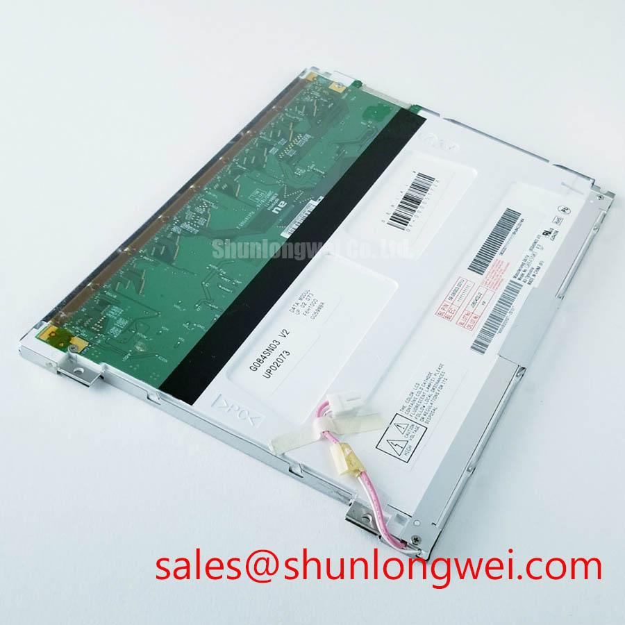
The G084SN03 V2 should be evaluated through its actual image interface and optical assembly rather than through model-number assumptions. A workshop test can begin with a known-good controller, a neutral grayscale pattern, and representative text screens. Observe black-level stability, gray-step separation, and any apparent inversion while viewing the panel from the intended operator position. If the display is used in an AGV or forklift cabin, ambient reflections and changing illumination can affect perceived contrast as much as the panel’s electrical drive conditions.
The supplied product context does not establish whether this model uses TN, IPS, MVA, or another liquid-crystal mode, nor does it confirm a symmetric viewing cone of 85° in all directions. Those characteristics must not be inferred from the product name. The system integrator should verify the official optical specification, contrast ratio definition, viewing-angle test method, surface treatment, and luminance data before publishing a system-level performance claim.
A surface described in the original documentation as anti-glare should be assessed under the actual enclosure window and lighting arrangement. External glass, protective films, dust, and operator-facing reflections can alter the result. An anti-glare surface may reduce specular reflection, but it does not remove the need to control the window angle, bezel shadowing, and internal light leakage in the finished display assembly.
Temperature testing should use grayscale ramps and natural text, not only a full-white screen. Liquid-crystal birefringence and switching behavior can change across the rated operating-temperature range. During the test, record the source clock, frame stability, image uniformity, and perceived gray transition behavior. Any observed jitter should be separated from panel behavior by checking the transmitter output, cable routing, connector seating, and controller timing with an oscilloscope against a known-good signal path.
💡 Pro Tip: Keep the differential display pairs closely coupled and length-matched through the flex and connector transition, then verify the completed assembly with the intended pixel clock and grayscale pattern.
Preventing Frame Lag and Image Smearing in Cryogenic Storage and Outdoor Industrial Facilities
Cold operation requires a distinction between an electrical display fault and a temperature-dependent optical response change. As liquid-crystal viscosity increases at low temperature, gray-to-gray transitions can appear slower, especially in scrolling text, map movement, or rapidly changing telematics data. The correct evaluation method is to place the complete panel and controller in the intended environmental condition, allow the assembly to stabilize, and compare fixed text, moving bars, and grayscale transitions at several brightness settings.
The factory information supplied for this product does not confirm an operating range from −30°C to +85°C, a guaranteed gray-to-gray response time, or a specific perimeter sealant construction. These values should be taken only from the applicable AUO specification. Enclosure designers should also assess condensation, pressure equalization, cable strain, and window sealing because the display module is only one part of the environmental system.
For outdoor or warehouse vehicles, backlight control should be reviewed together with the host electronics. The original panel documentation must be checked to identify whether the backlight input expects enable control, analog dimming, PWM dimming, or another control method. Do not assume that a controller designed for a different eight-inch-class panel will provide compatible polarity, current regulation, or logic thresholds.
When PWM is used by the verified system design, engineers should examine the selected frequency and duty-cycle behavior for visible flicker, camera-band interaction, acoustic behavior, and brightness linearity. The appropriate values are system-determined and depend on the backlight driver, camera requirements, optical load, and human-factors testing. A photodiode or calibrated luminance instrument is more useful than visual inspection alone when checking low-brightness linearity.
Frame lag and smearing can also be aggravated by a mismatch between panel timing and the display controller. Verify the controller’s pixel format, frame rate, synchronization behavior, and output amplitude from the original documentation. If a replacement controller is being considered, compare its timing tables with the panel requirements rather than relying on a similar connector appearance.
Aluminum Heat Spreader Placement Along Narrow Display Edges
Thermal integration should start with the actual heat sources in the finished assembly. Backlight electronics, local driver circuitry, processor boards, and enclosure surfaces can create uneven temperature distribution near the display edges. An aluminum spreader may help distribute heat when it is mechanically compatible, electrically safe, and thermally connected to the intended source. Its dimensions and attachment method must be established from the enclosure drawing and measured heat profile, not copied from a different display family.
The available factory data does not confirm an internal PMMA light guide, a particular LED lifetime classification, or an L70/B50 rating for the G084SN03 V2. Those properties should be obtained from the relevant AUO specification or backlight documentation. Engineers should avoid presenting a heat spreader as proof of a specific lifetime improvement unless the complete assembly has been tested under defined temperature, brightness, and duty-cycle conditions.
Use thermocouples or a suitable infrared measurement method to compare the bezel, backlight region, controller area, and enclosure contact points during representative operation. The measurement should account for emissivity, airflow, mounting pressure, and the effect of the protective window. A localized hot area may originate in the driver board, cable transition, enclosure, or nearby power electronics rather than in the LCD cell itself.
Thermal interface material selection is also system-dependent. The interface should fill the intended contact surface without stressing the glass, flex, or narrow edge of the module. Any chassis contact must preserve the manufacturer’s mechanical clearances and insulation requirements. If a heat spreader is bonded or clamped to the assembly, validate the result through thermal cycling and inspection for optical pressure marks, frame distortion, or connector loading.
For a broader explanation of panel construction, selection constraints, and common engineering misconceptions, the linked The Ultimate Guide to Industrial TFT LCD Technology can be used as a supporting technical reference. It should complement, not replace, the model-specific AUO documentation.
Controlled Differential Flex Routing and JEIDA or VESA Data Mapping
Before connecting the panel, compare the original harness pin by pin with the replacement documentation. The supplied product record does not confirm whether the G084SN03 V2 uses LVDS, TTL, a particular connector series, a defined logic supply, or a JEIDA or VESA data arrangement. The system integrator should verify the required supply voltage from the original panel documentation. A connector that mates mechanically can still carry a different power, enable, clock, or data assignment.
For an LVDS implementation confirmed by the original specification, route the differential pairs as controlled transmission lines through the board, flex, and connector area. Maintain a continuous reference structure, reduce unnecessary discontinuities, and keep noisy power-switching nodes away from the display pairs. The nominal differential impedance is determined by the panel interface and host design; a frequently used 100-ohm target should be treated as a design consideration only when it is specified by the complete link requirements.
Power sequencing should be checked with the panel manufacturer’s timing table. Do not assume a generic rise-time window or apply a 3.3 V or 5.0 V value without confirmation. Measure the logic rail, panel enable signal, backlight enable, and differential clock at startup and shutdown. The objective is to verify that the host controller does not present an invalid combination of power and control states to the module.
JEIDA and VESA mapping differences can produce incorrect colors, unstable grayscale, or split-screen artifacts even when the clock appears active. Check the bit order, color-channel assignment, differential polarity, clock polarity, and synchronization behavior against the known-good configuration. If the image is divided, offset, or populated with repeating noise, inspect mapping and signal integrity together rather than assigning the symptom to a single cause.
In a complete telematics assembly, the TCG084SVLPAANN-AN20 may be reviewed as a related display solution when comparing surrounding backlight or panel-system requirements. It is not a substitute designation for the AUO model, and compatibility must be established from the respective technical documents.
For cross-model sourcing, engineers can also examine G104VN01 V1 as a separate panel reference. Similar application language does not establish electrical or mechanical interchangeability. Confirm active-area dimensions, mounting geometry, connector position, interface protocol, power requirements, backlight control, and optical performance before considering any replacement path.