

Content last revised on September 10, 2026
Chassis Fastener Torque Considerations for Optical Mura Defects
With power removed, inspect the G084SN03 V0 display perimeter, mounting points, cable path, and mating connector before releasing any bezel fasteners; a pinched harness, uneven bezel pressure, or connector movement can resemble a panel fault during an industrial HMI repair.
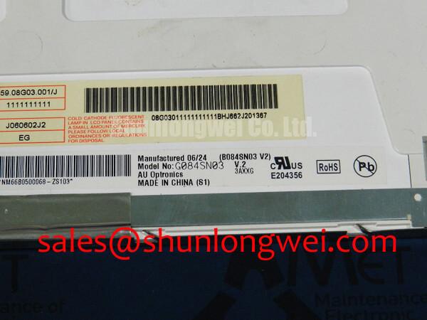
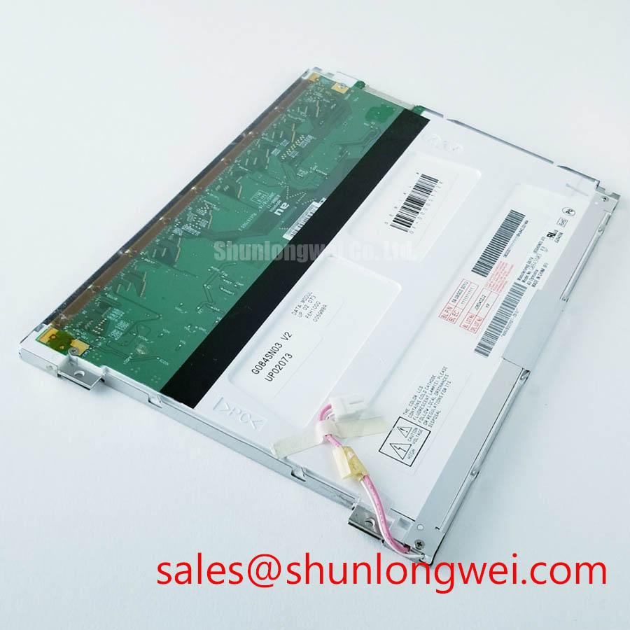
The G084SN03 V0 is an AUO TFT LCD Display Module. For a replacement assessment, technicians should match the installed unit by complete model marking, mechanical mounting arrangement, original cable assembly, controller compatibility, and power requirements documented by the host equipment manufacturer.
| Item | Product Information |
|---|---|
| Model | G084SN03 V0 |
| Manufacturer | AUO |
| Product Category | TFT LCD Display Module |
| Specification Status | Model identification provided |
Display replacement work should begin with evidence from the original machine rather than assumptions based on screen size alone. Photograph the panel label, connector orientation, cable routing, bezel contact areas, and controller board before removal. This establishes a reference when a black screen, intermittent image, uneven brightness, flicker, or image corruption is being investigated.
Before installing the G084SN03 V0 into a chassis, inspect whether the original bezel, bracket, and mounting holes hold the panel on a flat reference plane. Localized pressure from a distorted metal frame, trapped cable, bent bracket, or uneven fastener loading can create visible nonuniform areas on an LCD image. Such effects are often most noticeable on dark, grey, or single colour test patterns.
The 0.35–0.45 N·m M3 range is a Design Consideration for chassis hardware handling and must not be treated as an AUO factory mounting specification for this model. Final torque depends on the system bezel construction, screw length, thread engagement, bracket material, spacer arrangement, and instructions supplied for the host equipment. If the original equipment documentation specifies a different method, that documentation should govern the installation.
A controlled cross pattern is useful when the panel is held by multiple M3 positions. Bring each fastener into contact gradually, then apply the final system approved torque in alternating positions rather than fully tightening one corner first. After installation, inspect a uniform dark image and a uniform light image. If a new cloudy region, edge shadow, or local dark patch appears after fastening, release the assembly and evaluate frame flatness, cable clearance, and screw loading before attributing the issue to the display itself.
⚠️ Field Alert: Disconnect system power and allow stored energy in the host equipment to discharge before unplugging or reconnecting the display cable.
Cold ambient conditions deserve separate attention during fault replication. Liquid crystal response can appear slower at low temperature, and a screen that seems delayed or smeared during a cold start should be compared with behaviour after the equipment reaches its normal operating condition. Heater strips, if present in the complete terminal assembly, are system controlled items rather than confirmed features of the G084SN03 V0. The integrator should verify heater operation, temperature sensing, control logic, and warm up sequence from the original equipment documentation.
For industrial terminals where vibration or thermal cycling is a concern, the mounting evaluation should include the complete assembly. Check whether cable strain reaches the panel connector, whether the enclosure transfers bending force into the bezel, and whether the rear cover creates pressure when closed. This approach is more useful than making a single cause assumption from a visible optical symptom.
Surface Optical Treatment Considerations for High Ambient Readability
Evaluate screen readability with the machine in its intended lighting environment before deciding that the LCD itself lacks contrast. Reflection from a front window, protective cover, external overlay, or surrounding illumination can reduce apparent image quality even when the panel is receiving valid image data and its backlight system is operating correctly.
The provided official product information identifies the G084SN03 V0 as an industrial TFT LCD display module, but it does not confirm a specific anti glare coating, anti reflective coating, viewing cone, optical treatment, panel mode, or brightness value. Those attributes should not be assumed. The system integrator should verify optical characteristics from the original panel documentation and compare them with requirements for the installed equipment.
As a Design Consideration, an anti glare surface can reduce the appearance of direct reflections by diffusing incident light, while an anti reflective treatment is intended to reduce reflected light at an interface. Each can affect perceived sharpness, contrast, cleaning practice, and interaction with a touch overlay or protective window. A retrofit should therefore be assessed as a complete optical stack rather than as a panel only change.
Do not diagnose viewing behaviour from a single off axis observation. LCD appearance can be influenced by image content, polarizer orientation, host controller output, panel angle, front glass, and ambient lighting. Use static full screen patterns and compare the suspected assembly with a known good machine where possible. If contrast changes only after a front cover is reinstalled, inspect the cover condition and mechanical contact rather than changing panel settings without evidence.
Technicians assessing an industrial HMI or monitoring terminal can use the The Ultimate Guide to Industrial TFT LCD Technology as a general reference for display selection principles, optical terminology, and practical integration checks. It should support, rather than replace, the original equipment documentation for the G084SN03 V0.
Potential evaluation of this AUO display in railway passenger information or cab signalling equipment should remain equipment specific. Enclosure sealing, viewing distance, emergency operating requirements, controller compatibility, and applicable transport standards are determined at system level. The display module alone should not be represented as independently certified for complete system compliance.
Optical Luminance Evaluation and CCFL to LED Modernization Retrofit Pathways
When a terminal has a dim image, first separate image generation from illumination. Under safe service conditions, determine whether graphics remain visible under external light, whether the host controller continues to send image data, whether the original display cable is fully seated, and whether the equipment backlight supply behaves as expected. A dark screen can arise from several points in the display chain, including the panel, cable, power rail, driver board, controller output, or protective circuitry.
The supplied official information does not identify the G084SN03 V0 backlight type, backlight electrical requirements, luminance level, dimming method, ignition voltage, PWM capability, or service lifetime. Values associated with CCFL ignition, LED current regulation, PWM dimming ratios, and operating hour expectations must therefore not be assigned to this specific model without its applicable original datasheet.
A CCFL to LED conversion is a system modification, not an automatic display replacement procedure. It can involve a different driver topology, harness arrangement, enable control method, dimming command interpretation, thermal path, electromagnetic behaviour, and enclosure fit. Designers should verify the original panel backlight architecture and controller interface before considering any modernization route. A display symptom should not be used as evidence that an LED retrofit is compatible.
Where a repair investigation includes a related display topology, the TCG084SVLPAANN AN20 can be reviewed as a separate display solution. It is not presented as a direct substitute for the G084SN03 V0. Model specific mechanical, electrical, optical, and signal requirements must be checked against the original assembly.
For a suspected illumination issue, inspect for repeatable behaviour across cold start, warm operation, brightness commands, lid or bezel movement, and vibration exposure. Record whether the image disappears while the machine remains responsive, whether the condition changes with cable position, and whether a known good controller path produces the same result. This gives repair teams a traceable basis for deciding whether panel replacement, cable repair, driver repair, or controller diagnosis is appropriate.
Where another screen size or resolution class is being reviewed during material planning, G104VN01 V1 is available as a separate item for objective compatibility review. Any replacement decision should be based on confirmed drawings, interface documentation, electrical requirements, optical performance, and host firmware support.
Display Interface Synchronization and Logic Power Rail Verification
Before replacing the G084SN03 V0 for split image, colour corruption, rolling content, or intermittent blanking, inspect the signal path from the controller board to the panel connector. With the equipment safely de energized, check that the cable lock is engaged, the connector is correctly aligned, the harness has no sharp bend at the enclosure edge, and no mounting feature presses on the cable after the bezel is closed.
The official information provided for this model does not confirm a TTL 24 bit RGB interface, LVDS interface, logic supply value, pin assignment, power up timing, clock tolerance, differential impedance, or JEIDA and VESA data mapping. These details must be verified from the original AUO documentation for the exact G084SN03 V0 revision and from the host controller documentation. They should never be inferred from another AUO panel with a similar diagonal size or connector appearance.
As a Design Consideration, image artifacts can be associated with signal integrity, power sequencing, cable condition, controller timing, mapping configuration, or connector contact quality. Use an oscilloscope and a known good signal path where qualified personnel and safe access procedures permit. Compare supply stability and image timing against the original system requirements rather than applying generic voltage, timing, or impedance prescriptions.
If the display powers but shows unstable or divided content, establish whether the behaviour follows the panel, the cable, or the controller board by controlled substitution only after compatibility is confirmed. Recheck that the replacement label is exactly G084SN03 V0, because a panel that is physically similar can still require a different signal standard, timing arrangement, or power sequence.
For equipment repair documentation, record the original panel model, host controller part number, cable part number, connector orientation, observed symptom, and test result after reassembly. This information supports a disciplined decision between display replacement and deeper system troubleshooting without representing unverified interface values as factory specifications.