


Content last revised on September 12, 2026
Flashlight Dark-Shadow Optical Diagnostic to Isolate Logic vs. Backlight Failure Modes
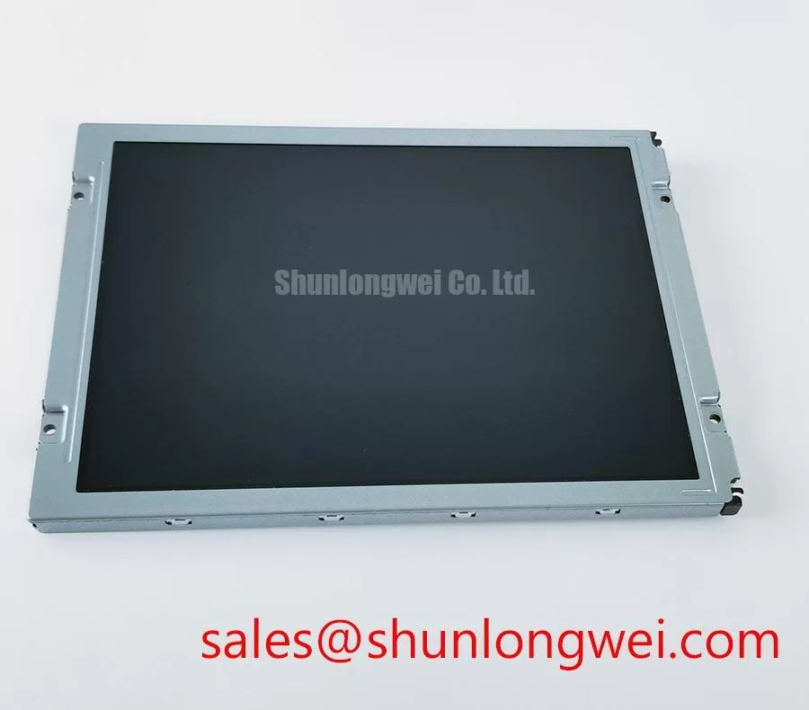
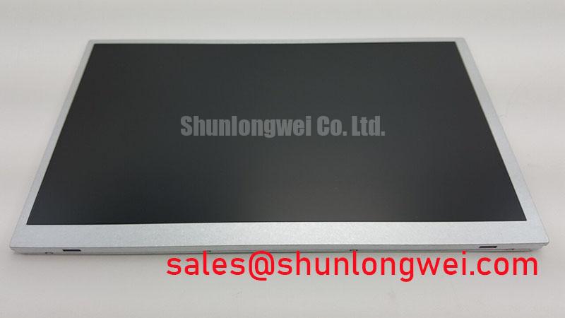
For a failed field display, apply a controlled full-screen test before replacing the panel. Display a white image, then primary red, green, and blue screens while observing the active area from a normal viewing position. Repeat the inspection with low ambient light so that isolated dark regions, vertical lines, missing pixel groups, and uneven illumination are easier to document. This three-colour check is a practical incoming-QA method, not an AUO factory acceptance limit for this model.
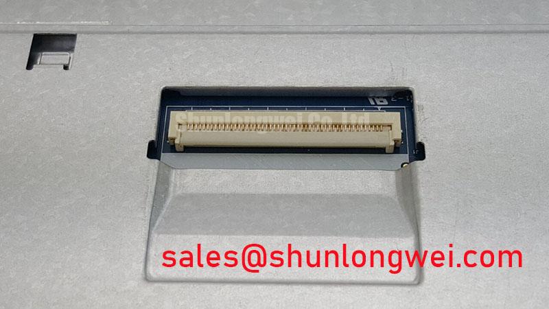
A 45-degree flashlight inspection can help separate an image-generation problem from an illumination problem. If faint image content remains visible beneath a dark screen, the display logic path and the illumination path should be investigated separately. If a line remains fixed while the test colour changes, inspect the signal connection, connector seating, cable alignment, and panel-side interface documentation. A dark area that changes with viewing angle or external illumination should not automatically be classified as a driver-chip defect. Verify the observation against a known-good controller and, where accessible, compare the signal path with an oscilloscope.
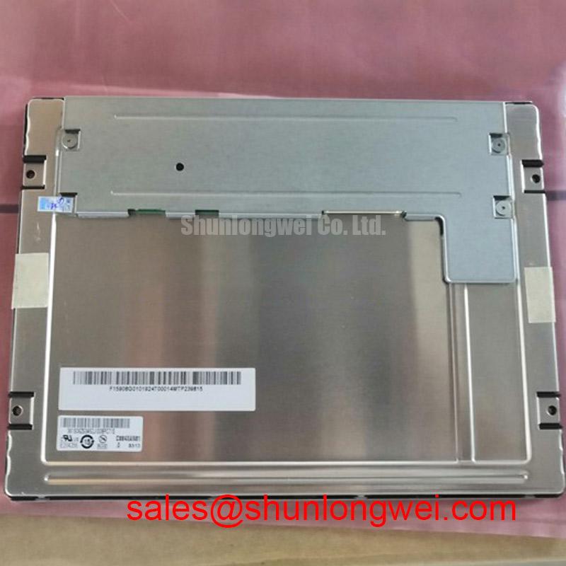
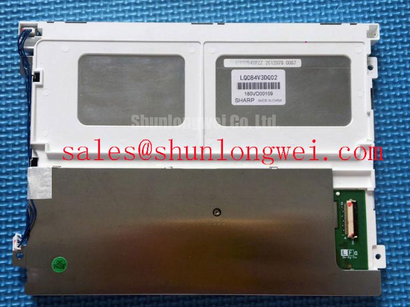
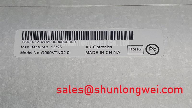
The supplied product data does not confirm LVDS, TTL, eDP, connector pin assignment, differential impedance, or clock-skew limits for the G090VTN02.0. Do not transfer a generic 100 ohm differential target or a generic 50 ps skew allowance to this panel without a matching interface specification. In a high-EMI cabinet, the system integrator should verify cable construction, termination, shielding, grounding, and measured signal quality under the actual enclosure conditions. The related G104VN01 V1 may be reviewed as a separate display option, but electrical and mechanical compatibility must be established independently.
Suppressing Acoustic Capacitor Buzz and EMI Emissions Across PWM Frequencies
Backlight troubleshooting should start with identification of the installed backlight architecture rather than an assumption that the panel uses CCFL or LED technology. The supplied factory data for this listing does not confirm a backlight type, cold-ignition voltage, PWM frequency range, dimming ratio, acoustic behaviour, brightness, sunlight contrast, or half-life. The system integrator should verify the required backlight supply and driver from the original panel documentation.
When a display produces audible noise, inspect the external driver, mounting surfaces, cable routing, and enclosure coupling while changing the brightness command only within the documented operating range. A sound that follows a control frequency may originate in the driver or surrounding mechanical structure rather than the LCD module itself. EMI evaluation should be performed with the complete operator station assembled, because cable routing, bonding, filtering, enclosure construction, and switching edges influence radiated and conducted emissions. The display module itself should not be represented as independently certified to an industrial EMC standard.
For a hazardous petrochemical Zone-2 operator station, the panel is only one part of the equipment assessment. The enclosure, power supply, wiring method, user interface, thermal management, and applicable hazardous-location certification remain system-level responsibilities. The linked LMS700KF01-001 can be examined as a related display-system component, while its interface and electrical role must be confirmed from its own documentation.
Thermal Cycling Degradation of Polarizer Adhesives and Sealant Gasket Integrity
Thermal screening should record the panel image before and after the planned temperature exposure, using the same test patterns and camera position for each inspection. Look for changes in uniformity, persistent lines, edge leakage, visible separation, condensation effects, and response behaviour during temperature transitions. The supplied specifications do not assign a temperature range, liquid-crystal response time, grey-to-grey value, polarizer construction, adhesive qualification, sealant composition, or gasket rating to this model. These characteristics must not be inferred from the model number.
At low temperature, a slower visual response can be associated with the display system, controller timing, backlight behaviour, or the panel itself. Record the test condition and compare the result with the original equipment documentation rather than applying a generic GTG limit. When the unit is integrated into a sealed monitoring terminal, designers should verify heat spreading, condensation control, cable flexibility, and the temperature capability of the mating connector. Any heater strip, if used by the equipment, requires system-level control and validation; its setpoint and timing cannot be prescribed from the available panel data.
Signal timing also requires documentation-led verification. The factory information provided here does not specify TTL or LVDS transmitter timing, clock jitter, setup time, hold time, or power-sequencing requirements. Confirm the controller output format and the required enable sequence before applying power. 💡 Bench Tip: Use ESD protection and keep the display cable fully aligned before locking the connector, because an offset insertion can create intermittent image faults that are difficult to reproduce.
For broader enclosure, sealing, and environmental integration considerations, engineers may consult Industrial Display & HMI Solutions. That engineering reference does not replace the model-specific AUO documentation or the certification requirements of the completed operator station.
Chassis Fastener Loading and Optical Mura Inspection
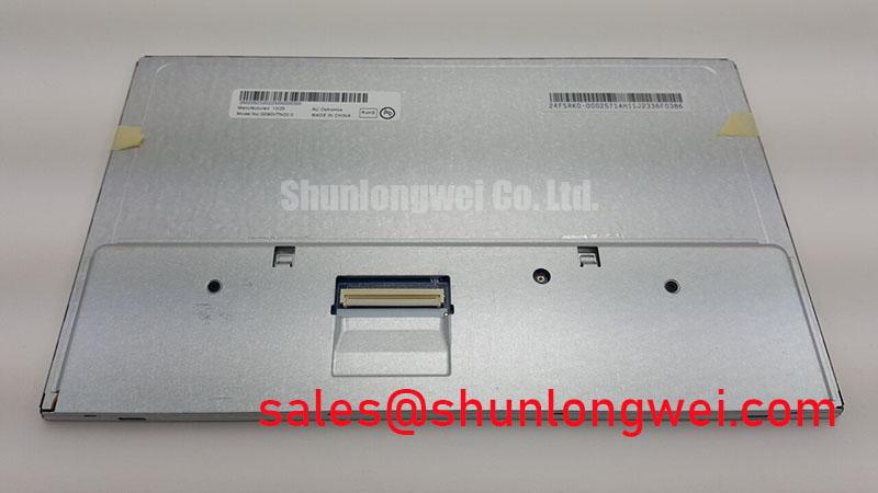
Mechanical installation should begin with the original chassis drawing and the panel manufacturer’s fastening instructions. The supplied factory data confirms the TFT-LCD display module category but does not provide bezel dimensions, mounting-hole locations, allowable chassis flatness, fastener size, tightening torque, or compression limits. Consequently, a generic M3 torque range must not be treated as an official value for the G090VTN02.0.
During a replacement fit check, confirm that the bezel supports the module evenly and that no cable, connector, or edge region is trapped by the chassis. Tighten fasteners progressively in a cross-pattern only when the original mechanical specification authorizes that method. Inspect the panel with a dark field and uniform white field after assembly. Localized bright or dark regions may result from mounting stress, enclosure distortion, illumination non-uniformity, contamination, or signal behaviour, so the diagnosis should be confirmed by loosening the assembly under controlled conditions and comparing the optical pattern.
In cold environments, response changes should be evaluated with the complete display assembly, including the controller and backlight driver. Do not claim a specific thermal operating window, GTG performance, anti-glare property, sunlight contrast ratio, or optical half-life for this AUO model without the applicable datasheet. For procurement and repair teams, the key compatibility checks remain the original interface documentation, backlight requirements, mechanical drawing, environmental rating, and the equipment manufacturer’s approved replacement record.