Content last revised on October 21, 2026
Incoming Benchtop Inspection: Bonded Edge and Flex Integrity
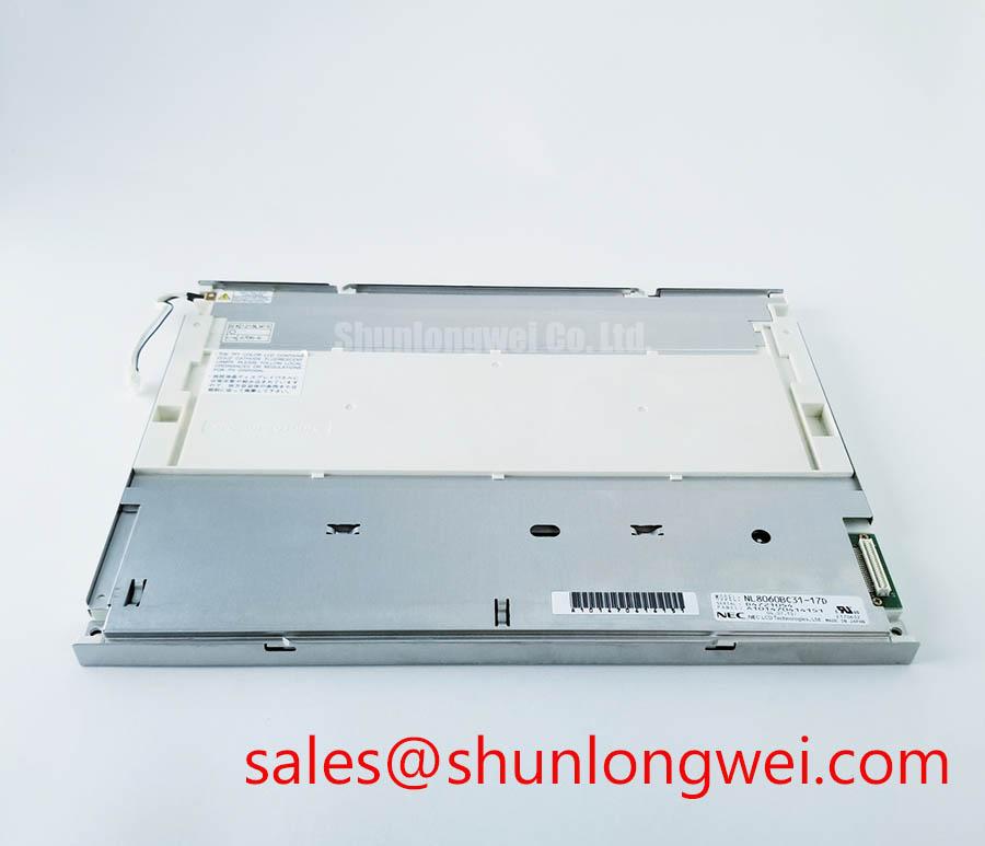
- Check the panel label against NL10260BC19-01D before removing the service unit.
- Record bezel clearance, connector alignment, and gasket contact before applying power.
- Use an ESD-safe bench and inspect the display across full-screen red, green, blue, white, black, and gray images.
- Confirm the controller supply, interface pinout, backlight arrangement, and power sequencing from the original equipment documentation.
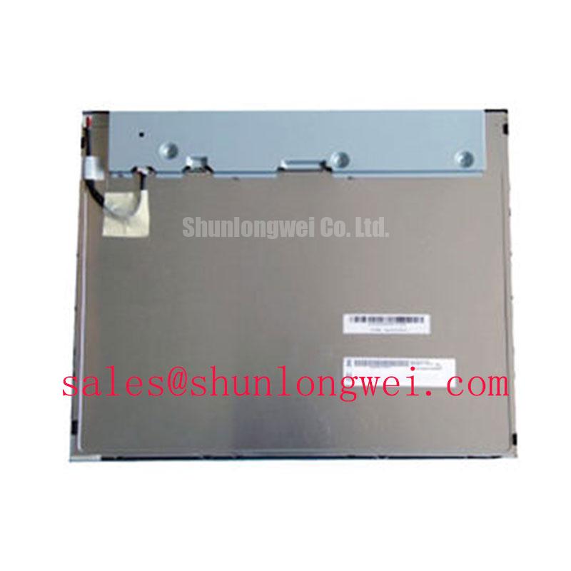
The NEC NL10260BC19-01D is an industrial grade LCD/HMI panel in a TFT-LCD active matrix color display module format. Its supplied specification baseline is identified as a decoded baseline with a standard form factor. The baseline does not establish a voltage rating, interface type, physical dimensions, luminance value, contrast ratio, viewing angle, response time, backlight type, or operating temperature range. Those values must be matched to the original panel documentation before electrical substitution.
| Manufacturer | NEC |
| Model | NL10260BC19-01D |
| Product category | Industrial Grade LCD/HMI Panel |
| Module construction | TFT-LCD Active Matrix Color Display Module |
| Specification status | Decoded Baseline / Standard Form Factor |
| Unlisted integration data | Consult the original panel documentation for electrical, optical, mechanical, and interface values |
Start the optical inspection with a controlled primary-color sequence: red, green, blue, white, black, and a neutral gray field. A fixed pattern makes intermittent pixel defects easier to separate from image-source problems. Look for isolated bright or dark pixels, vertical line interruptions, edge discoloration, and groups of pixels that change when the flex area is gently observed without applying mechanical pressure.
A 45-degree flashlight check is useful when the panel appears dark but the backlight path is uncertain. Sweep the beam across the front surface in a darkened bench area. A faint image or localized shadow can indicate that image information is present while illumination is abnormal; a completely inactive image path requires a separate controller, cable, and power-sequencing check. This test does not identify a single failure mechanism by itself, so compare the result with a known-good signal path whenever possible.
COG and TAB edge regions deserve visual inspection under low-angle light. Look for lifted flex edges, uneven compression marks, contamination near the bonding zone, or a line defect that follows a regular driver boundary. Avoid probing or pressing the bonded area. The appropriate action is to document the defect position, repeat the color sequence after a complete restart, and compare the result with the panel’s original operating assembly.
When a controller provides PWM backlight control, a 200 Hz to 1 kHz PWM range may be used as an engineering recommendation for bench evaluation, not as an official specification of this model. Check duty-cycle linearity while observing audible noise, camera-banding artifacts, and visible flicker. The backlight driver, panel wiring, and controller firmware must be assessed together because a suitable frequency for one assembly may not be suitable for another.
💡 Bench Tip: Keep the flex cable flat and fully seated before locking the connector, and discharge static safely before touching the panel or controller interface.
Flush-Mount Open-Frame Bezel Integration & Perimeter Gasket Shock Isolation
Flush mounting should begin with an unloaded bezel trial. Place the panel into the chassis opening without tightening the fasteners, then check whether the viewing area remains centered and whether the perimeter gasket contacts evenly. A hard point at one corner can transfer stress into the display stack and create localized brightness variation or dark-field mura.
The supplied record does not provide an outer bezel drawing or approved fastener torque for this model. As a general mechanical design consideration, a small M3 fastener should be tightened in a cross pattern with controlled torque; the 0.35 to 0.45 N·m range specified for this installation study is an engineering reference, not a confirmed NEC production value. The final setting must follow the chassis drawing, gasket compression requirement, and service manual.
Optical bonding, perimeter sealing, and dust protection should be treated as system construction choices unless they are explicitly documented for the replacement assembly. If the equipment uses an optically bonded cover, inspect the bond edge for bubbles, moisture paths, and uneven contact after thermal exposure. If it uses a separate cover lens, maintain a clean air gap and prevent the gasket from touching the active viewing area.
For cold equipment, allow the display assembly and chassis to reach a stable condition before judging response behavior. Liquid crystal response can become visibly slower in sub-zero environments, while a heater or enclosure control can introduce local temperature gradients. Evaluate the complete panel and enclosure rather than assigning a temperature limit to the model without a supporting specification.
Wide Symmetric Viewing Cone for Multi-Angle Consoles
Multi-angle console testing should use observers positioned above, below, left, and right of the normal viewing axis. Check grayscale steps, skin-tone or warning-color reproduction, and black-level uniformity from each position. The 85°/85°/85°/85° viewing-cone figure is a target value to verify from the applicable panel datasheet; it is not included in the supplied baseline for this model.
TN, IPS, and MVA panels can show different grayscale behavior as the viewing direction changes. A replacement decision should therefore compare the actual panel technology, polarizer behavior, surface treatment, and controller gamma configuration. The Tianma Industrial TFT Display Solutions reference provides useful industry context for evaluating industrial display optics, but it does not replace the model-specific documentation.
For a bright control-room or outdoor-facing enclosure, test the display under the equipment’s real lighting geometry. A contrast result above 500:1 at 50,000 lux should be treated as a defined acceptance target only when required by the system specification; it must not be presented as a confirmed rating for NL10260BC19-01D. An anti-glare surface can reduce reflected images, but it may also alter apparent sharpness and black-level perception. Record both the measured optical result and the operator’s viewing position.
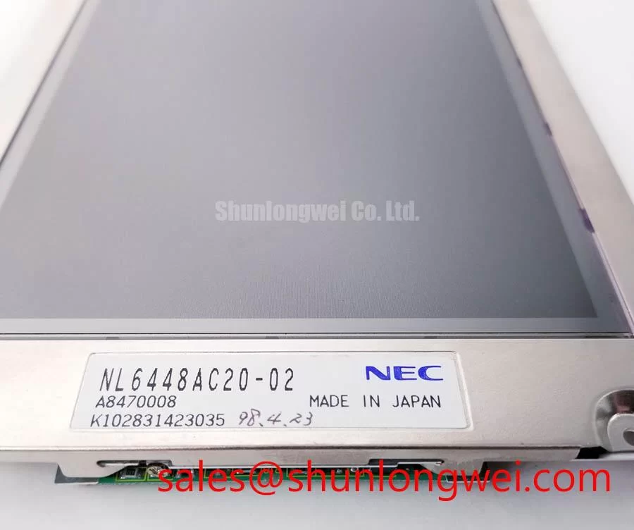
When comparing a same-size or same-resolution service option, engineers can place NL6448BC33-24 beside the NEC unit in the evaluation matrix. Compare connector position, active area, mounting envelope, controller compatibility, and backlight requirements rather than treating nominal display size alone as interchangeability.
Mitigating Gray-to-Gray (GTG) Response Time Escalation during Cold-Start Machine Power-Up
Cold-start verification should capture the first image transition after power-up, then repeat the test after the enclosure reaches its normal operating condition. Observe gray-to-gray motion, scrolling text, cursor movement, and alarm graphics. Slow transitions, temporary color shifts, or residual images can originate from panel temperature, controller timing, power sequencing, or signal integrity, so the complete assembly should be monitored together.
The stated evaluation window of −30°C to +85°C should be used only when it is supported by the relevant product documentation and system test plan. It is not an automatic operating-temperature claim for this model. If a heater is present in the host equipment, its control strategy should avoid creating a sharp temperature gradient across the viewing area. The perimeter seal should also be inspected after thermal cycling for separation, moisture entry, or visible edge deformation.
Backlight service assessment requires the actual driver configuration, current regulation method, thermal environment, and brightness acceptance point. A curve described as 50,000 hours to 50 percent brightness is a vendor-specific lifetime claim that must be supported by the applicable backlight or module documentation; it should not be inferred from the NEC model number. During evaluation, record startup brightness, uniformity, flicker, driver noise, and image stability under the intended control signal.
Power sequencing deserves a direct bench comparison with the original assembly. Verify that the controller enables the panel, backlight, and image source in the required order, and check for white-screen startup, dropped frames, or residual images during shutdown. The system integrator should confirm supply voltage and interface timing from the original panel documentation rather than assuming compatibility from the connector appearance.
For a CNC operator panel or robot teach pendant, the surrounding controller, cable strain relief, bezel, and backlight driver determine much of the field behavior. The companion display reference TCG084XGLAAPNN-AN00-S can be reviewed as a separate system-topology reference, while Industrial Display & HMI Solutions provides additional integration context for enclosure, optical, and service evaluation.