

Content last revised on September 25, 2026
Aluminum Heat Spreader Sizing & Thermal Interface Placement along Narrow Display Edges
Map the enclosure’s narrow-edge contact zones with removable thermal indicators while the display assembly operates under its expected brightness and ambient-load conditions. A localized temperature rise at one edge can point to uneven chassis contact, concentrated backlight-driver heat, restricted airflow, or excessive pressure from a mounting rail rather than a panel-level electrical fault.
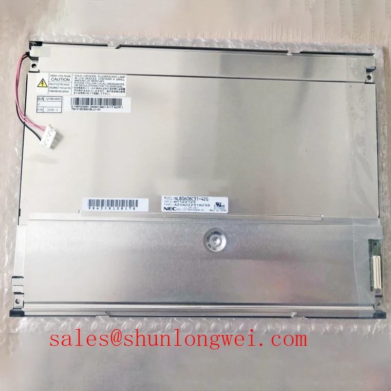
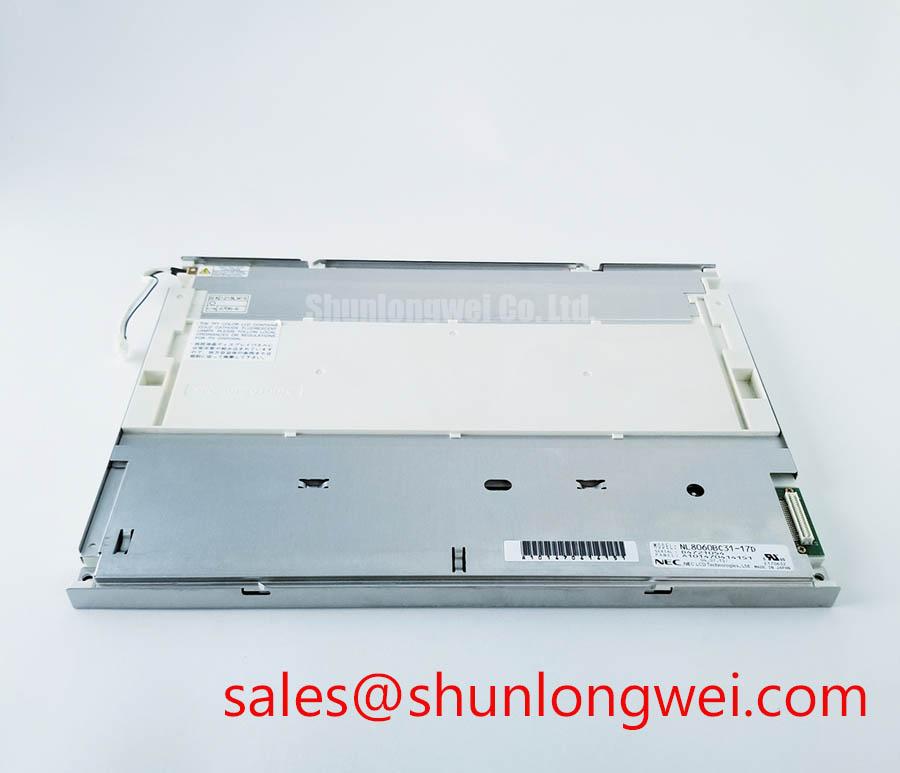
The NL8060BC31-17D is officially identified as an NEC industrial TFT-LCD panel in a TFT-LCD active matrix color display module package. Its supplied official product information does not define a heat spreader, optical stack material, ambient temperature range, contrast ratio, sunlight readability value, anti-glare treatment, or backlight lifetime rating. These properties should therefore remain part of the host-equipment evaluation rather than being assigned to the panel as fixed factory specifications.
Design Consideration: when a narrow-bezel display is retained by metal side rails, thermal spreading should be assessed together with mechanical loading. A rail that transfers heat effectively but presses unevenly against the display perimeter can create visible non-uniformity, especially on dark or low-gray test patterns. The useful objective is stable edge temperature without turning the enclosure into a point-load structure.
Inspect the existing equipment for insulating tapes, compliant interface pads, stand-offs, and rail contact marks before transferring any thermal hardware to a replacement panel. Their location often reveals whether the original design used the chassis as a heat path or simply as a structural reference. Substitute interface materials only after their thickness, compression behavior, electrical isolation requirement, and contact pattern have been checked against the original assembly.
For display terminals exposed to bright ambient light, engineers should verify the installed panel’s contrast behavior and surface finish under the actual enclosure window. A stated sunlight readability value, anti-glare coating, or optical contrast figure must come from the original panel documentation or validated system test, not from a general industrial-panel assumption. The NEC Industrial TFT Display Solutions reference provides useful background on industrial display technology considerations, while final optical acceptance remains dependent on the complete panel, cover lens, bonding method, and enclosure geometry.
A nearby product reference such as NL6448AC33-17 can support a structured comparison of physical outline, mounting points, display interface, and optical requirements. It should not be treated as a direct replacement without confirming the original equipment’s mechanical and electrical documentation.
Where a thermal concern accompanies brightness instability, separate the investigation into three observations: panel surface temperature distribution, backlight supply behavior, and image content stability. A temperature-sensitive image shift can be examined with fixed grayscale patterns, while a brightness change that follows the backlight control path should be checked at the system level. This separation prevents a chassis-contact issue from being mistaken for a data-interface problem.
Dynamic Contrast Ratio Stabilization & Liquid Crystal Birefringence Temperature Tracking
Display fixed black, white, neutral-gray, red, green, and blue patterns while observing the image from the installed viewing position and from each permitted service angle. Record whether an apparent contrast shift follows temperature, backlight command changes, panel orientation, or the incoming pixel stream, because these observations lead to different inspection paths.
The official parameters for NL8060BC31-17D establish the product as an industrial active-matrix TFT-LCD module, but do not state the liquid-crystal mode, viewing-angle specification, contrast ratio, response-time range, anti-glare etching, or brightness-control method. It would be inaccurate to assign TN, IPS, MVA, symmetric viewing cones, or a declared contrast performance to this model without the original NEC technical documentation.
Design Consideration: liquid-crystal optical behavior can change as panel temperature changes, and the apparent result can be more noticeable in dark gray areas than in saturated colors. Engineers should compare a warmed system with a cold system using the same test image and the same enclosure conditions. If the image becomes stable after thermal equilibrium, the next step is to determine whether the host system needs an operational delay, image compensation routine, or an enclosure-level thermal review. The required approach is system-determined and should be validated on the actual equipment.
When the panel is used in a precision image terminal, grayscale consistency needs to be evaluated with the complete signal chain intact. Confirm the output format selected by the host controller, the timing configuration stored in the display controller, and the expected data mapping. A mismatch between the transmitter format and the panel receiver format can create incorrect colors, banding, or abnormal tonal transitions that resemble an optical defect.
Inspect backlight dimming behavior separately from video behavior. Visible periodic modulation can originate in the backlight control stage, its enable sequence, an unstable dimming command, supply ripple, or an unsuitable interaction with the host image sensor or camera system. Oscilloscope comparison against a correctly operating unit can help distinguish an irregular control waveform from a panel image issue. The original documentation must establish the applicable backlight supply, enable, and dimming requirements for this model.
If the equipment architecture includes a related display variant such as NL8060BC31-41, compare each unit’s original interface and backlight requirements independently. A similar NEC naming pattern is not evidence of shared connector assignments, electrical timing, or optical behavior.
💡 Pro Tip: Route and retain differential display pairs as matched pairs through the connector transition so that mechanical cable movement does not introduce intermittent pixel-clock distortion.
For cold-start investigations, keep the diagnostic sequence practical. Power the complete host system through its normal sequence, display a static grayscale target, observe the first minutes of operation, and repeat after the assembly reaches its normal operating condition. Any operational temperature compensation belongs to the equipment design and should be confirmed against measured image performance rather than assumed from panel category alone.
Chassis Fastener Torque and Mounting Stress to Eliminate Optical Mura Defects
Loosen and re-seat the chassis fasteners in a controlled cross-pattern while showing a uniform dark-gray image, then inspect whether localized clouds, edge brightening, or pressure marks change with mounting stress. This direct observation is more useful than assuming that every non-uniform region originates from the LCD cell or backlight assembly.
The supplied official information does not define the mounting-hole size, fastener type, mounting torque, bezel envelope, or permissible chassis deformation for NL8060BC31-17D. Any general M3 mounting torque guidance should not be treated as an NEC factory torque rating for this exact module. The original mechanical drawing and the host-equipment service procedure govern the final installation method.
A cross-pattern tightening sequence is valuable because it distributes mounting force progressively across the frame. Installers should avoid using a rail, screw head, washer, or cable clamp as a lever against an active display area. Check that the panel seats on its intended support surfaces and that no enclosure feature bears against a region not intended for structural contact. A panel can remain electrically functional while visible image quality is affected by uneven frame loading.
Measure the chassis opening and support positions when replacing an older display assembly. A nominally similar module can differ in locating features, connector clearance, board depth, or edge profile. These differences can alter both stress distribution and cable routing. In service work, transfer only those spacers, seals, and brackets that belong to the original mechanical stack and do not interfere with the replacement module’s documented mounting surfaces.
For a differential display interface, a commonly used Design Consideration is controlled differential impedance around 100 Ω ± 10%, subject to the panel interface requirement and the host-board stack-up. Signal-pair skew should also be evaluated in relation to the actual pixel-clock timing budget. The system engineer should verify waveform quality at the receiver location, particularly where a long harness, adapter board, or high-noise enclosure environment is involved.
Do not treat a dark image region as proof of a single mechanical cause. Compare the defect with fasteners slightly relaxed, with the display placed on a flat non-conductive support, and with the original video source held constant. If the defect remains spatially fixed despite controlled mounting changes, inspect the signal path, backlight behavior, surface contamination, and enclosure-window pressure before reaching a repair decision.
Equipment used for surgical navigation or ultrasound diagnostic display functions may require controlled image verification procedures defined by the equipment manufacturer. The NL8060BC31-17D should be evaluated as an industrial display module within that broader system process; its supplied product parameters do not establish medical certification, diagnostic-image compliance, or equipment-level safety approval.
Incoming Benchtop Inspection: COG/TAB Anisotropic Conductive Film (ACF) Integrity
Connect the module through the correct documented interface, display solid red, green, and blue fields, and photograph the result under repeatable exposure settings before installation. This three-color bench sequence makes persistent lines, color-channel loss, unstable regions, and spatially fixed artifacts easier to compare without assigning a cause prematurely.
Follow the color test with a black image in reduced ambient light, then use a flashlight at an oblique angle around the bezel and cover-window interface. A shadow pattern that changes with external illumination can indicate an enclosure, cover lens, or surface-interface effect, while a defect that remains constant under controlled image content deserves further signal and panel inspection. This method separates observations; it does not prove a specific internal failure mechanism.
The official specification supplied for NL8060BC31-17D does not identify COG, TAB, anisotropic conductive film, connector pin count, connector position, or cable-bend limits. These terms should therefore be used as inspection vocabulary only when supported by the original module construction data. Avoid pressing on the display perimeter or bonded areas during diagnosis, since applied pressure can change the visible symptom and obscure the original condition.
Inspect the host connector, latch mechanism, cable strain relief, and cable routing with the system unpowered. Look for incomplete latch engagement, uneven insertion depth, damaged cable shielding, excessive bend near the connector, and chassis interference during enclosure closure. Repeated flexing near a connector is an integration risk that should be addressed through routing and strain relief determined by the host assembly design.
For suspected signal-integrity issues, compare the differential clock and data behavior with a properly operating signal path using appropriate probing methods. Ringing, amplitude loss, timing displacement, or intermittent transitions may indicate a cable, connector, transmitter, termination, or grounding-path issue. They do not independently identify a panel defect. Confirm JEIDA or VESA data-format alignment only from the original panel and controller documentation, since an incorrect format selection can produce image errors without any physical damage.
System integrators evaluating the NEC NL8060BC31-17D for industrial HMI, monitoring, surgical-navigation, or ultrasound-display equipment should document the complete integration baseline: mechanical fit, connector compatibility, input timing, supply sequence, backlight control, enclosure stress, and image acceptance criteria. For wider integration context, see Industrial Display & HMI Solutions. NEC corporate display information is also available through NEC Display Solutions.