Content last revised on October 2, 2026
TV101WXU-N91 BOE Industrial LCD Display Module
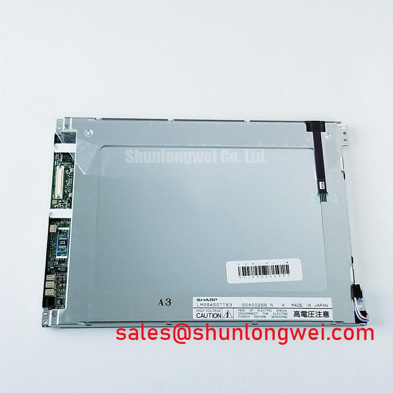
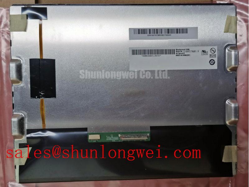
Begin a replacement inspection by checking the panel label against TV101WXU-N91, then compare the housing, connector position, visible surface, and mounting interface with the removed display before applying power. The documented product identity is BOE, with the product category listed as an Industrial Grade LCD/HMI Panel. Its package description is TFT-LCD Display Module, and the available factory record is marked Official Factory Spec Verified.
This page is intended for engineers evaluating a display replacement in industrial HMI equipment, operator stations, vehicle telematics consoles, and control cabinets. The published information does not establish a panel supply voltage, display resolution, interface type, luminance value, viewing angle, operating temperature range, backlight construction, or mechanical dimensions. The system integrator should verify each of those requirements from the original panel documentation and the equipment manufacturer’s service information before installation.
| Model | TV101WXU-N91 |
| Manufacturer | BOE |
| Product category | Industrial Grade LCD/HMI Panel |
| Package description | TFT-LCD Display Module |
| Specification status | Official Factory Spec Verified |
For a same class comparison during a retrofit review, engineers may place TCG084SVLQAPNN-AN30-S beside the existing panel record, but compatibility must be established from interface, electrical, optical, and mechanical documentation rather than model naming alone. A different display size or connector arrangement can require changes to the bezel, cable routing, controller configuration, or sealing method.
Shielded FFC/FPC Flat Flexible Cable Grounding across 360-Degree Connector Shells
Before connecting the display, inspect the flexible cable for creases, uneven insertion, exposed shielding, and contamination on the contact area. The connector shell and cable shield should be assessed as a complete high frequency return path. This is a Design Consideration, not a published electrical specification for TV101WXU-N91. The objective is to control common mode current and reduce the possibility of pixel jitter, horizontal noise bands, or intermittent image loss when the display is installed near variable frequency motor drives.
A 360 degree shield termination is useful when the cable and connector system actually supports it. The enclosure bonding method, chassis reference, cable length, and routing distance from motor power conductors remain system determined. Engineers should avoid assuming that a drain wire or a single pigtail connection provides the same behavior as a low impedance perimeter termination. Verification should be performed with the final cable assembly in place, using the known good signal path as the reference.
Common mode ferrite suppression can be evaluated as an Engineering Recommendation when conducted noise remains after cable routing and shield bonding have been checked. The ferrite selection, location, impedance curve, and thermal environment belong to the equipment design. No ferrite type or suppression value is specified here for this BOE module. An oscilloscope comparison at the display input can help separate signal integrity issues from a panel, timing controller, or power sequencing problem.
Cold operation requires additional caution. Liquid crystal response and the timing behavior of the complete display assembly can change at low temperature, while cable flexibility and connector contact pressure may also be affected. The supplied factory information does not confirm a temperature range for TV101WXU-N91. If the equipment may operate below room temperature, the integrator should obtain the original environmental specification and evaluate gray transition behavior, image retention, and startup timing across the actual enclosure temperature range. A heater strip, if used by the system, requires independent control validation and must not be treated as an integrated feature of this panel without documentation.
The display power and signal interface must be confirmed before energizing the assembly. Do not infer a required supply voltage or interface standard from the TFT-LCD package description. A compatible backlight or driver assembly may be evaluated separately, including NL10276BC30-18, but its electrical relationship to TV101WXU-N91 must be verified from the relevant technical documents.
Preventing Frame Lag and Image Smearing in Cryogenic Storage and Outdoor Industrial Facilities
When a removed panel has been stored in a cold vehicle, warehouse, or outdoor cabinet, allow the assembly condition to stabilize according to the equipment maintenance procedure before applying power. Condensation risk depends on temperature, humidity, enclosure ventilation, and the condition of the front seal. The available factory record for TV101WXU-N91 does not specify a storage or operating temperature range, so a numerical cold start limit should not be assigned to this model.
Low temperature can increase the apparent response time of liquid crystal transitions. Operators may describe the result as frame lag, smearing, or slow gray change, but the observation alone does not identify a defective panel. Record the ambient and panel surface conditions, confirm the video source timing, and compare the suspected unit with a known good display using the same signal path. This approach helps distinguish a temperature dependent optical response from transmitter timing, cable loss, or system software behavior.
The perimeter seal, bezel compression, and cabinet gasket should be reviewed during installation. These are Design Considerations for outdoor and heavy equipment applications, not confirmed construction details of the BOE module. Uneven mechanical pressure can distort the visible area or create localized optical nonuniformity. Excessive compression can also compromise the intended sealing interface, while insufficient compression can allow dust or moisture to reach the display cavity.
Direct sunlight testing should use the actual machine enclosure and viewing direction. A contrast ratio above a particular value, anti glare performance, and optical bonding capability have not been supplied as official specifications for TV101WXU-N91. They must therefore be measured or confirmed from the applicable panel documentation rather than stated as guaranteed characteristics. An anti glare surface may reduce reflected light, but it can also alter perceived sharpness and black level under a particular incident angle.
For a display installed in an earthmoving equipment telematics cabin, the practical assessment includes vibration exposure, bezel support, cable strain relief, sunlight readability, and condensation control. The panel should not be described as qualified for a specific mining shovel or vehicle platform unless the equipment manufacturer has completed that qualification. Engineers should validate image stability during cold startup, normal operation, and thermal transition with the final enclosure and harness installed.
Maintenance Note: Check the cabinet airflow path and perimeter gasket condition during scheduled service so dust accumulation or a displaced seal does not create an avoidable display reliability problem.
Full Screen Primary Color AOI Screening: Stuck Sub Pixels and Background Uniformity Audit
A replacement inspection can use full screen red, green, blue, white, black, and neutral gray test images to document visible defects before the panel is installed. This is a practical Design Consideration for incoming inspection and does not create a factory acceptance limit for TV101WXU-N91. Use the same test source, cable, controller, and viewing distance for each comparison so that the record reflects the panel rather than a changing signal path.
During the first pass, examine the full field for persistent bright or dark points, vertical lines, horizontal bands, edge shading, and broad luminance variation. A single color screen can make a sub pixel defect more visible, while a white or gray field can reveal broad uniformity changes. Do not assign a failure cause from appearance alone. Pixel behavior may be influenced by the source timing, connector contact, display controller, or the panel assembly itself.
The second pass should inspect the panel at normal viewing position and then from a controlled off axis position. Changes with viewing direction can be a property of the display’s optical design rather than a sudden defect. The available specification data does not identify the panel mode, viewing angle, contrast ratio, anti glare treatment, or optical bonding method. Those characteristics should be confirmed before an optical acceptance limit is written into a repair procedure.
For the third pass, a flashlight held at approximately 45 degrees can help locate shadows, edge leakage, contamination, or localized surface irregularities when the display is showing a dark field. This technique is a visual screening method, not a proof of a COG driver fracture or backlight failure. If a line defect changes with cable movement, temperature, or connector pressure, isolate the harness and controller variables first. If the defect remains with a verified signal path, record its location and operating condition for supplier or equipment level evaluation.
AOI records should include the model label, test image, signal source, visible defect position, ambient conditions, and photographs taken at consistent exposure. Do not claim a specific defect count or uniformity tolerance unless that limit is stated in the applicable factory documentation. The technical principles behind TFT display selection, interface review, and common evaluation errors are discussed in The Ultimate Guide to Industrial TFT-LCD Technology.
Grayscale Inversion Mitigation and Optimal Viewing Direction Alignment
Viewing direction should be checked from the actual operator position rather than from a product label assumption. The available factory record does not confirm whether TV101WXU-N91 uses TN, IPS, MVA, or another liquid crystal mode. It also does not specify a symmetric viewing cone, grayscale inversion limit, contrast ratio, or optical compensation layer. Those properties must be verified from the original BOE documentation before a panel is accepted for a particular HMI layout.
If grayscale inversion appears when the operator views the screen from above, below, or from the side, document the angle and displayed gray pattern. The observation may relate to panel optical behavior, cover glass reflection, installation tilt, image processing, or the viewing direction of the original design. Designers should align the display with the primary operator sightline and validate critical alarms and trend colors at the working position, while avoiding a claim that the panel offers IPS or MVA wide angle performance without supporting data.
TTL or LVDS terminology should not be inferred from the TFT-LCD module category. The transmitter clock, data hold time, lane arrangement, voltage levels, and power sequence are interface specific. The system integrator should verify the required interface and supply voltage from the original panel documentation. During commissioning, an oscilloscope or protocol appropriate measurement can compare clock stability, data transitions, enable timing, and reset behavior with a known good assembly.
A white screen at startup or residual image after shutdown may involve power sequencing, backlight control, display enable timing, controller reset behavior, or stored charge in the system. These symptoms do not establish a single failure cause. Verify the documented sequence for the display and controller, then observe the signal and supply behavior during startup and power removal. The final sequence must be determined by the equipment electronics and validated under the intended temperature and load conditions.
For control cabinets and heavy equipment telematics displays, the mechanical installation should release stress evenly across the bezel and support points. The cable should have strain relief that prevents connector loading during vibration, while the front seal should remain continuous around the visible opening. These integration practices support the equipment design but are not additional factory specifications for TV101WXU-N91.