


Content last revised on September 26, 2026
Preventing Localized Display Compression and Dark-Field Mura
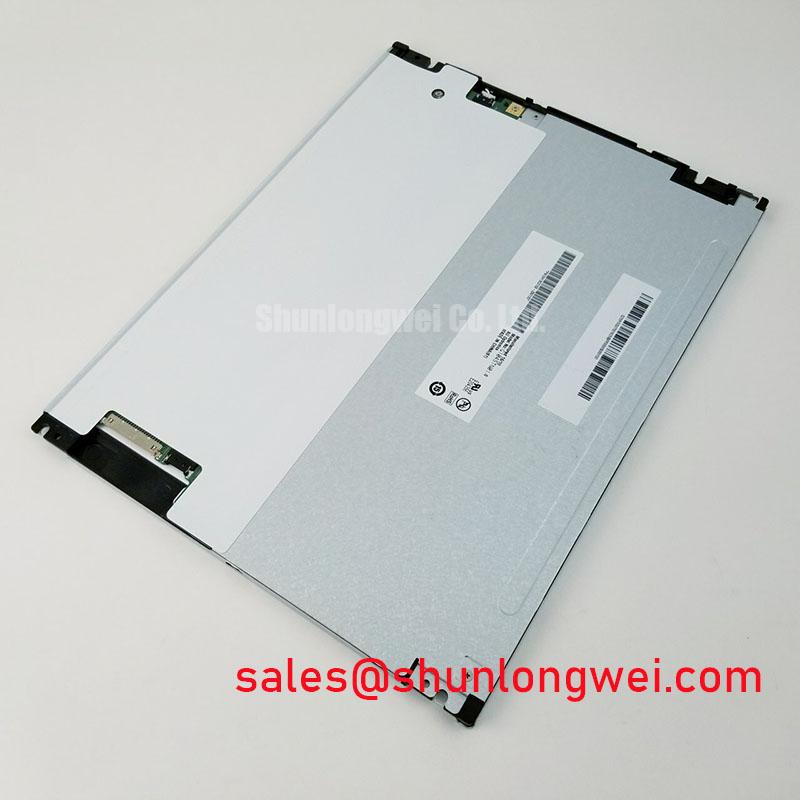
Inspect the bezel opening and connector orientation before fitting the G104STN01.3 into an existing display chassis. AUO identifies this part as an industrial-grade TFT-LCD display module (Official Specification). The supplied product information does not establish its active area, outline dimensions, electrical ratings, signal interface, backlight construction or surface treatment, so those items need confirmation against the original panel documentation before a replacement is approved.
Start a mechanical fit check with the module unpowered. Compare the candidate panel’s outer envelope, mounting features, connector clearance and visible area with the removed unit and the enclosure drawing. A bezel that appears to fit can still press unevenly on the display stack once its fasteners are tightened. As a Design Consideration, leave the optical area free of concentrated chassis pressure and verify the assembly in its installed orientation, not just on a workbench.
Display a uniform dark field after assembly and look for patches that change when bezel pressure is relieved. That observation can help distinguish a mounting-sensitive artifact from a mark that remains unchanged with the panel outside the enclosure. It does not, by itself, identify a light-guide defect: front-window reflections, display drive settings and the image source can also affect what the technician sees. Record whether the artifact follows the panel, the enclosure or the video path before changing the mechanical stack.
If the chassis uses cross-pattern fastener tightening, follow the equipment manufacturer’s mounting instructions rather than assigning a torque to G104STN01.3 without a confirmed panel drawing. Check that brackets sit flat, cable routing does not lift one edge, and protective films or enclosure seals do not intrude into the viewing area. These are integration checks, not AUO mounting specifications.
For a railway passenger information terminal or cab display being evaluated for compatibility, physical fit is only the first gate. The viewing window, installation angle and ambient light can expose optical differences even when the replacement seats correctly. Treat sunlight contrast and any anti-glare requirement as equipment-level acceptance criteria; the supplied product information does not provide a sunlight contrast rating for this model.
Evaluating Anti-Glare and Anti-Reflective Requirements in Bright Ambient Light
Inspect the installed front surface under the lighting conditions the equipment actually encounters. Reflections from the cover window, an air gap or nearby illumination can obscure text independently of the LCD image. An anti-glare finish scatters reflected light, while an anti-reflective treatment aims to reduce reflection; neither treatment should be attributed to G104STN01.3 without confirmation in its original documentation.
A useful comparison keeps the image, viewing position and cover-window arrangement consistent. Observe small text, dim graphics and dark backgrounds from the operator’s normal position, then repeat at the viewing angles required by the enclosure. If grayscale appears to reverse at an angle, document the direction and compare it with the original unit. Do not infer a TN, IPS or MVA panel mode from that symptom alone. Viewing-angle limits and optical mode must come from verified panel data or controlled measurements.
The backlight needs a separate check. Measure its behavior using the equipment’s existing driver and dimming controls, while verifying that the driver’s electrical requirements match the original panel documentation. Uneven illumination, flicker or a brightness change during warm-up warrants examination of the driver output, connections and display assembly as separate possible contributors. The supplied information does not confirm the backlight type, current rating or brightness-maintenance curve for this revision, so a service-life figure would not be a sound basis for procurement.
Touch behavior belongs to the complete display assembly, not automatically to the LCD module. If the equipment includes a capacitive or resistive overlay, identify its controller and front-window construction separately. Gloved operation and water on the surface should be tested against the equipment’s acceptance procedure rather than inferred from the G104STN01.3 designation.
Checking Edge Temperature and Backlight Integration
After confirming the approved drive arrangement, run a stable image and inspect for localized heating around the display edges and its mounting enclosure. A warm edge is a prompt to compare the installed unit with a known-good assembly under the same drive and ambient conditions; it is not proof of a particular internal rail, LED layout or light-guide material. Those construction details are not established by the supplied product information.
As a Design Consideration, provide a clear thermal path around the display while avoiding brackets that press on its viewing area. Verify the result at the enclosure’s expected operating conditions and with its normal brightness controls. If the equipment uses an additional front window, consider how that window and its sealing arrangement affect both heat retention and perceived brightness. The final enclosure design and its acceptance limits remain system-determined.
When assessing another panel for the same equipment, G104VN01 V1 is a separate model to compare, not a confirmed drop-in replacement. Check its mechanical drawing, connector and pin assignment, supply requirements, image timing, optical performance and backlight drive against the original assembly before drawing a substitution decision. A similar model designation cannot establish interchangeability.
Temperature and illumination checks should also reflect the complete HMI enclosure. For a broader framework for evaluating display installation conditions, see Industrial Display & HMI Solutions. Any environmental margin claimed for a finished display still requires testing of that finished equipment; no temperature, sunlight-readability or lifetime rating for G104STN01.3 is supplied here.
Verifying Video Timing and Noise Margin in Vibration-Prone Enclosures
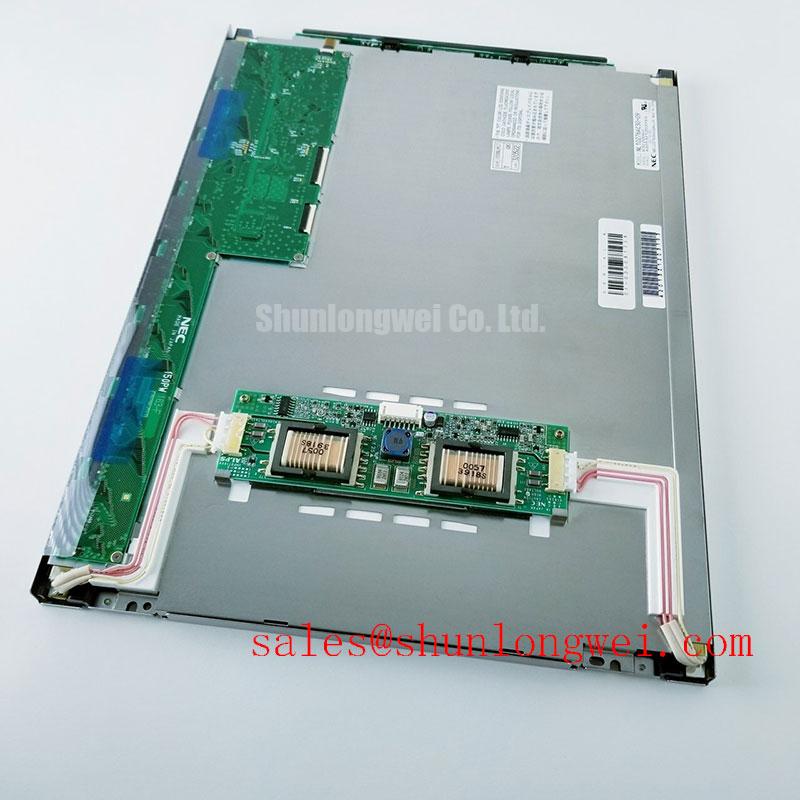
Identify the original display connector and obtain the panel pin assignment before attaching a host board or test fixture. The supplied product information does not establish whether G104STN01.3 uses LVDS, TTL or another video interface. The system integrator should verify the required supply voltage, signal levels, power sequence and backlight controls from the original panel documentation. Matching connector shape alone is not an electrical compatibility check.
If the documented interface is LVDS, compare the transmitter’s channel mapping, clocking and color-data format with the panel requirements. A JEIDA-versus-VESA mapping mismatch can alter colors or grayscale without producing an obviously absent image. If the documented interface is TTL, evaluate its parallel-data timing instead of applying differential-pair assumptions. In either case, keep the host timing configuration and the panel revision tied to the same approved drawing.
Use test images that expose subtle faults: grayscale ramps for tonal transitions, fine vertical detail for sampling errors and uniform fields for intermittent bands. Unexpected tones can originate in source formatting, timing configuration or display-drive behavior. They should not be assigned to the timing controller or gamma calibration without comparing the source signal and a known-good display path.
💡 Pro Tip: Keep documented differential pairs consistently routed and verify their clock and data margins at the installed connector before treating pixel jitter as a panel fault.
In a vibrating enclosure, check connector retention, cable strain relief and the shield-termination arrangement specified by the equipment design. Where the host uses a differential video link, discontinuities and noise coupling can reduce the eye-diagram margin; the appropriate impedance target, skew budget and test limits must come from the approved interface documentation. Ferrites or shielding changes are Design Considerations to validate in the complete system, not guaranteed remedies for horizontal bands or electromagnetic interference.
Finish the fault isolation with the panel installed and the surrounding equipment operating in its normal modes. Compare the image at the host output and panel connector, then inspect for changes when cables are supported or nearby drives switch states. This separates a possible connection or signal-integrity issue from an optical artifact without claiming that the LCD module independently meets an equipment-level EMC requirement.