

Content last revised on November 11, 2026
NEC NL10276AC30-09 Identification and Incoming Inspection
- Disconnect panel power and inspect the LVDS connector, cable retention, and exposed contacts before disturbing the display harness.
- Check mounting brackets for uneven pressure, displaced cushioning, and cable routing that pulls against the connector.
- Display solid white, black, red, green, and blue patterns to document pixel defects, edge shadows, and localized color differences.
- Record brightness settings, ambient conditions, and warm-up behavior so subsequent optical comparisons use the same test conditions.
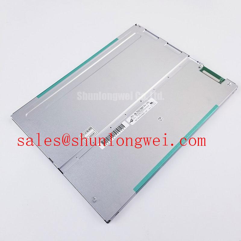
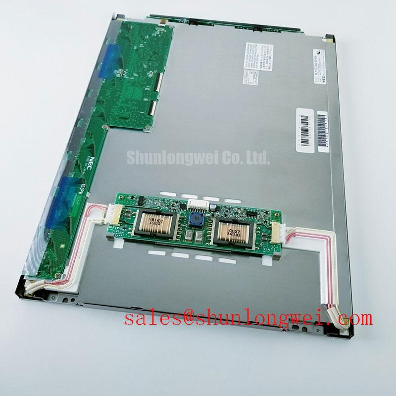
The NL10276AC30-09 is a NEC TFT-LCD active matrix color display module with a 15 inch diagonal, 1024 x 768 resolution, and an LVDS interface. For incoming inspection, separate panel condition from host-controller behavior: a clean test-pattern source helps distinguish optical defects from image-generation or transmission problems.
| Specification | Product identification and integration baseline |
|---|---|
| Manufacturer | NEC |
| Part Number | NL10276AC30-09 |
| Diagonal Size | 15 inch |
| Resolution | 1024 x 768 |
| Interface | LVDS |
| Product category | LCD Display / Industrial HMI Display Panel |
| Form factor | TFT-LCD Active Matrix Color Display Module |
| Integration details requiring the model-specific datasheet | Supply voltage, connector pinout, timing, mechanical dimensions, backlight configuration, numerical luminance, and operating temperature limits: Consult Datasheet. |
These identification parameters establish the starting point for evaluating the NEC NL10276AC30-09 LCD display; they do not establish electrical interchangeability with another panel. The engineering procedures below are Design Considerations, not additional manufacturer specifications.
Diffuser Film & Prism Sheet Thermal Buckling Prevention under Continuous Full-Duty Operation
Inspect a uniform gray image before and after the assembled display reaches a stable operating condition, looking for edge brightening, broad shadows, or color patches that develop with enclosure temperature. Repeat the observation with unchanged brightness and viewing geometry. A changing pattern can help identify temperature-sensitive assembly stress, but it does not by itself identify a particular internal optical sheet or material.
As a Design Consideration, examine how the mounting frame transfers load into the panel perimeter. Brackets should support the intended mounting features without twisting the module or pressing the viewing surface. Compare the image with the bezel loosely positioned and then correctly secured; a reproducible change associated with fastening deserves mechanical investigation before an electrical repair is attempted. Use the equipment manufacturer's assembly requirements rather than assigning a generic tightening torque.
Heat-spreading rails are an enclosure-level option, not an established feature of this NEC module. When evaluating them, map enclosure and panel-edge temperatures first, then check whether the proposed thermal path reduces local heating without adding frame distortion. Size, contact pressure, and electrical clearance belong to the assembled-system design. Thermal improvement should be demonstrated by measurements under the intended brightness and duty conditions.
External cover glass and optical bonding also change mechanical loading and heat flow. Engineering Recommendation: assess adhesive compatibility, differential expansion, and service access before changing the original stack. Optical bonding alone does not establish a moisture-tight enclosure. Inspect cable entries, bezel joints, and cover seals separately, and use the external Tianma Industrial TFT Display Solutions resource for industrial-display context, not as evidence of this model's internal construction.
Optical Luminance Degradation Curve & CCFL-to-LED Modernization Retrofit Pathways
Measure a repeatable luminance baseline before interpreting a dim image as backlight deterioration. Keep the displayed pattern, measurement position, brightness command, warm-up condition, and instrument geometry consistent. Record center and peripheral readings together with visible color differences; a single center measurement can miss an edge-darkening problem that affects text readability.
As a Design Consideration, build a maintenance trend from comparable measurements rather than assigning a projected service life from appearance. Changes can involve the illumination system, optical contamination, drive settings, or panel transmission. Neither an LED lifetime classification nor an MTBF value should be attached to the NL10276AC30-09 without applicable manufacturer evidence. Such metrics also describe different things and should not be treated as interchangeable maintenance deadlines.
A CCFL-to-LED conversion is an assembly redesign, not a consequence of matching the panel diagonal. Establish the installed illumination arrangement from the actual assembly documentation before considering a conversion. Evaluate optical coupling, illumination distribution, driver control, heat rejection, and mechanical retention as a complete change. An improved center reading is insufficient if the conversion produces visible edge bands or alters the usable dimming range.
For brightness-control testing, sweep the supported control range while watching low-level uniformity, flicker, and audible behavior. If modulation is involved, correlate the optical response with the driver's control waveform; frequency and dimming limits must come from the selected driver and equipment requirements. Do not transfer generic ignition voltages or PWM ratios into this panel's specification.
Long-duration HMI checks should include representative static screens followed by neutral patterns to assess temporary image retention and recovery. Screen blanking or content movement can be evaluated at the application level without promising immunity to retention. Where a touch overlay is involved, the Industrial display Application Guide provides complementary touch-selection context; it is not a lifetime qualification report for this LCD.
Suppressing Pixel Jitter & Horizontal White Lines Induced by Adjacent 400V Motor Drives
Compare the displayed fault with motor-drive operating state while keeping the image source unchanged. Record whether pixel instability or horizontal lines coincide with switching activity, cable movement, or a brightness change. Proximity to a motor drive is a useful diagnostic clue, not proof that electromagnetic coupling caused the fault.
As a Design Consideration, inspect the LVDS route for damaged shielding, interrupted chassis connections, unsupported spans, and close parallel runs beside power conductors. Preserve differential-pair geometry and the equipment's intended return paths. Shield termination changes or common-mode suppression components should be evaluated through system measurements because they can alter signal quality as well as noise coupling.
💡 Bench Tip: With power isolated and ESD precautions in place, seat the display cable squarely and engage its specified retention mechanism before restoring power.
Check connector engagement without repeatedly flexing the cable at its exit. Provide strain relief that follows the harness design and allows assembly movement without transferring force into the contacts. A stationary panel interconnect should not be treated as a continuous-flex cable; any moving installation needs a harness qualified for its actual motion. Intermittent lines that respond to cable position warrant comparison with a known-good signal path rather than an immediate panel diagnosis.
For possible replacement evaluation, compare NL10276AC30-02 against the complete electrical and mechanical requirements; the related designation alone does not validate a direct replacement. For a CNC operator panel or robot teach pendant, designers should verify connector orientation, LVDS mapping, active-area alignment, enclosure fit, and illumination controls before approving either unit. During waveform checks, use suitable differential probing and compare receiver timing against the controller requirements instead of imposing an arbitrary jitter margin.
Mitigating Gray-to-Gray (GTG) Response Time Escalation during Cold-Start Machine Power-Up
Compare moving gray transitions at initial power-up with the same transitions after thermal stabilization, keeping the source timing and image sequence unchanged. Slower liquid-crystal response at lower temperature can produce trailing or smeared transitions, but a delayed image can also involve the controller or illumination startup. Observe those behaviors separately.
As a Design Consideration, perform temperature testing within the approved limits of the complete display assembly. Select test conditions from the equipment qualification plan rather than assigning a generic industrial temperature range to this model. If auxiliary heating is considered, its control, temperature sensing, and mechanical attachment require separate validation; it is not a presumed panel accessory.
Capture panel supply, interface activity, and illumination enable together when investigating startup white screens. Compare their order with the prescribed panel sequence and the host's startup behavior. During shutdown, check whether image data and illumination are removed in the intended order and whether the supply decays cleanly. Residual images alone do not identify a failed panel; repeatable timing observations provide a stronger basis for corrective work.
Evaluate LVDS transmitter timing across the equipment's approved temperature conditions, including clock stability and data alignment at the receiving interface. A controller with TTL-side signals still requires the correct conversion and panel-side LVDS mapping; those interface names do not establish compatibility. Retain the validated timing configuration during optical comparisons so controller changes do not obscure temperature-related response differences.
Finally, compare text and gray ramps from the actual operator viewing positions without assuming an IPS or MVA architecture. Viewing-angle color changes should be distinguished from localized pressure effects and illumination nonuniformity. After thermal stabilization, inspect mounting pads, cable restraint, and bezel contact for displacement, then repeat the same gray-transition sequence to determine whether the observed lag follows temperature, mechanical stress, or startup timing.