Content last revised on September 10, 2026
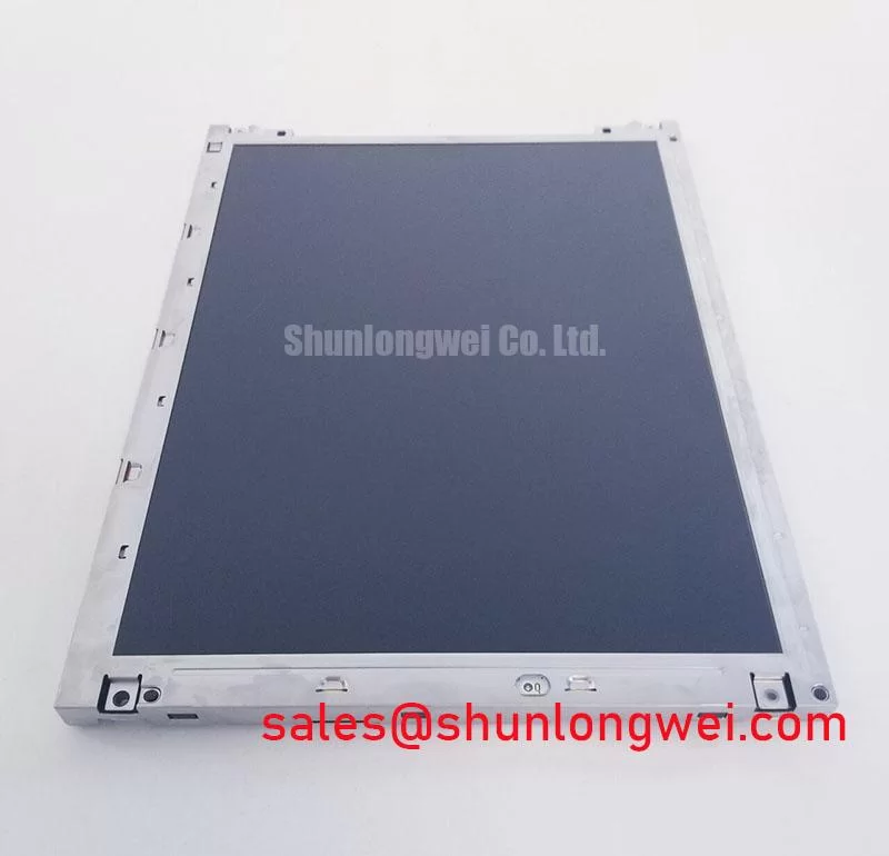
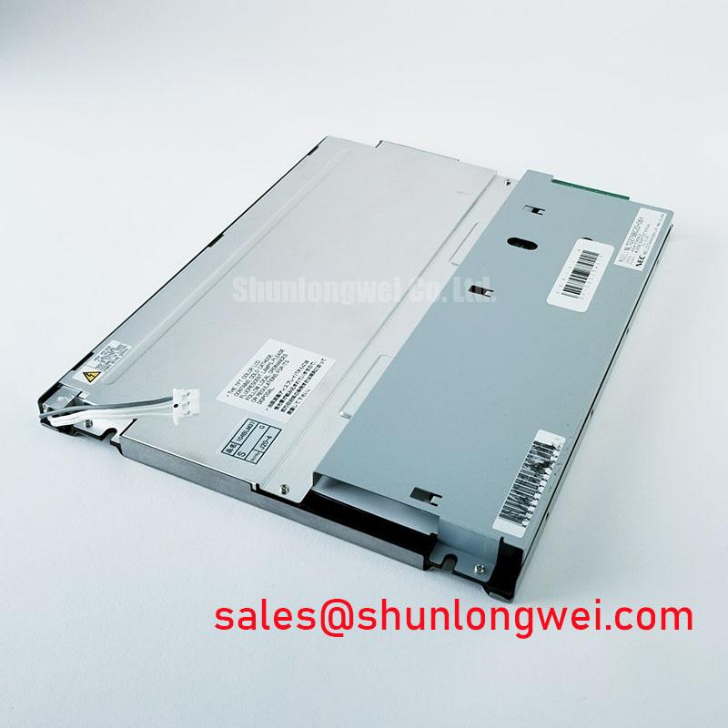
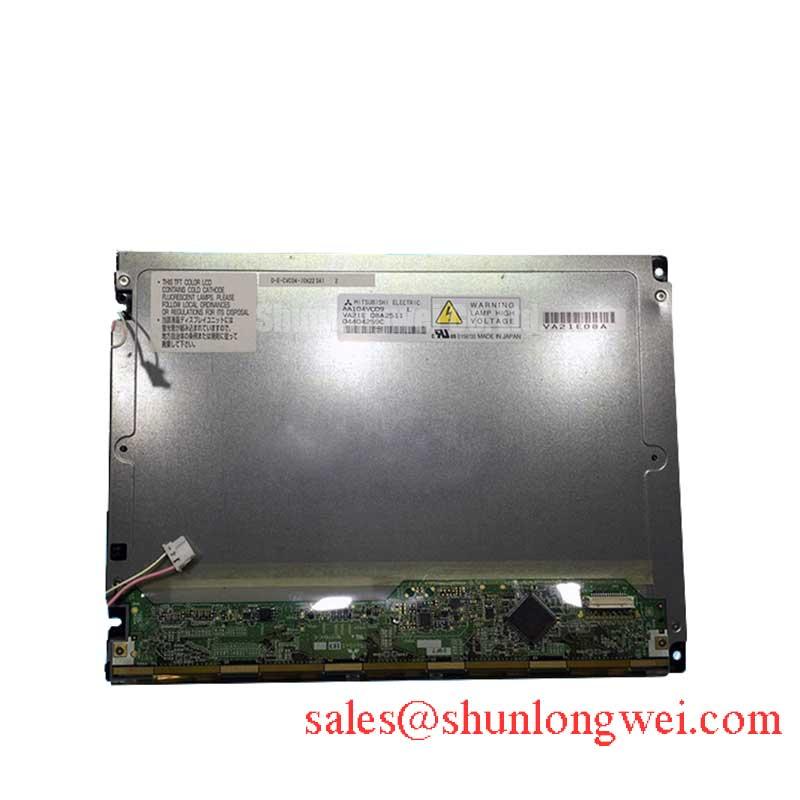
NEC NL10276AC30-58F Display Module
Before installing the NEC NL10276AC30-58F, isolate the display assembly, inspect the bezel and connector area, and compare the replacement panel’s identification label with the original equipment documentation. This part is identified as an Industrial Grade LCD/HMI Panel in a TFT-LCD Display Module format. Electrical interface, optical performance, and mechanical envelope details should be confirmed against the original panel documentation before the unit is connected to an AGV or forklift telematics controller.
| Manufacturer | NEC |
| Model | NL10276AC30-58F |
| Product category | Industrial Grade LCD/HMI Panel |
| Construction category | TFT-LCD Display Module |
This page separates confirmed product identity from system-level integration guidance. The available factory data does not confirm a specific resolution, active-area size, backlight technology, viewing-angle class, supply voltage, connector pinout, or interface mapping. Those values must not be inferred from the model reference alone. For a service engineer, this distinction is important because a visually similar industrial display can still differ in timing, connector assignment, mounting geometry, or controller compatibility.
Constant Luminance Output Control and L70/B50 Reliability Verification
In a vehicle-mounted display, luminance stability is assessed at the complete assembly level rather than by the panel name alone. The NL10276AC30-58F is identified as a TFT-LCD display module, but the supplied factory data does not state an L70 or B50 value, LED current rating, backlight lifetime, optical plate material, or thermal derating curve. These values should therefore be treated as verification items during equipment qualification, not as guaranteed characteristics of this product page.
For an AGV or forklift telematics display, begin with a controlled visual inspection after the unit has reached the intended operating condition. Look for uneven brightness, localized darkening, color drift, or a bright region concentrated near one narrow edge. A thermal camera can help locate temperature gradients around the bezel, flex area, backlight driver region, and enclosure contact points. This check does not prove a backlight failure by itself; it provides evidence for comparison with a known-good assembly and with the original equipment’s normal thermal pattern.
A practical Design Consideration is to provide a clear heat path around the display perimeter without pressing directly on the active glass. Aluminum spreader rails may be evaluated where the enclosure design creates a narrow hot area, but the rail size, contact method, insulation, and fastening method remain system decisions. The objective is to reduce localized thermal concentration while avoiding frame distortion and excessive stress on the module. Any proposed thermal modification should be checked during cold start, continuous operation, and enclosure reassembly.
L70 and B50 are reliability terms that require a defined test condition, drive current, ambient temperature, optical measurement method, and failure criterion. Without those conditions, a numerical lifetime statement would not be technically meaningful. Engineers qualifying this NEC display module should request the applicable original documentation or perform a controlled luminance study on the assembled unit. Record initial luminance, operating temperature, drive condition, and measurement location so that later readings remain comparable.
Sub-zero operation creates a separate verification issue. Liquid-crystal response can become slower as temperature falls, and a display may show more visible image trailing during rapid scene changes. The supplied product information does not establish a guaranteed operating range or a specific gray-to-gray response curve for this model. If the equipment can remain outdoors or in an unheated warehouse, designers should verify cold-start behavior using the real controller, enclosure, cable harness, and display settings.
A heater strip may be evaluated as a system-level measure when condensation or slow cold response affects usability. Its placement should warm the assembly evenly and should not create a local optical hot spot. Heater control, insulation, airflow, and enclosure sealing must be validated by the equipment designer. A temperature transition test should also check whether moisture forms on the front surface, inside the enclosure, or near the cable entry. Do not apply heat abruptly to a visibly wet assembly.
Wide Symmetric Viewing Evaluation for Multi-Angle Consoles
Viewing angle is often decisive in a vehicle console because the operator may read the screen from a seated, standing, or offset position. The supplied factory specification for the NL10276AC30-58F does not identify the panel mode as TN, IPS, MVA, or Super-IPS, and it does not provide an official 85°/85°/85°/85° viewing-angle rating. Those characteristics must be checked in the original datasheet or measured on the exact display assembly rather than assigned from general LCD terminology.
During incoming evaluation, display a neutral gray scale, saturated red, green, and blue fields, and a high-contrast text screen. Observe the image from the operator’s actual eye positions rather than from a single perpendicular viewpoint. Note grayscale inversion, color shift, loss of shadow detail, and changes in apparent luminance. This procedure helps distinguish an interface or gamma issue from an optical viewing-angle limitation.
TN panels can show more obvious grayscale inversion at off-axis positions, while IPS and MVA families can provide different compromises between contrast, color stability, response behavior, and black-level uniformity. These are general display-technology considerations, not confirmed attributes of the NEC model listed here. If an AGV or forklift console requires a wide viewing zone, the system integrator should compare measured image quality at the installed angle, with the final cover glass, anti-glare surface, and enclosure lighting in place.
Surface treatment also changes the result. An anti-glare surface can reduce reflected warehouse lighting, but it may alter perceived sharpness and black level. The correct evaluation should use the final front window and any protective overlay. A display that appears acceptable on a workbench can show distracting reflections after installation beneath overhead lighting or in an open vehicle cabin.
Mechanical mounting deserves equal attention. Uneven bezel pressure can produce local luminance variation, color nonuniformity, or visible mura. The frame should sit flat against the intended support, with fasteners tightened progressively and without forcing a panel corner into alignment. Gaskets should seal the opening while allowing the assembly to remain free from concentrated stress. When the original mounting drawing is unavailable, designers should verify clearance, gasket compression, frame flatness, and connector bend radius using the replacement assembly before final fastening.
For service planning, the similarly referenced NL10276BC16-06 can be reviewed as a separate same-class sourcing reference. It should not be treated as an automatic substitute. The technician must compare active area, resolution, connector position, pin assignment, timing, mounting dimensions, backlight requirements, and controller compatibility against the original system documentation.
Glass Substrate and Driver-Bump Stress Prevention
LCD glass and bonded driver regions require careful handling during inspection and installation. The supplied product data confirms the display-module category but does not disclose internal bonding construction, driver-bump geometry, glass thickness, or a mechanical shock rating. Avoid assigning a specific internal structure to the NL10276AC30-58F. Instead, use external inspection and controlled electrical testing to determine whether the assembly is suitable for the equipment’s mechanical environment.
Start the bench check with a clean, stable image source and a repeatable primary-color sequence. Display red, green, and blue fields individually, then use a neutral gray field and a fine text pattern. Look for fixed vertical lines, intermittent bands, a half-screen difference, missing color regions, or defects that change when the flex area is disturbed. Do not press the glass or bonded edge to reproduce a fault. Mechanical probing can convert an intermittent condition into permanent damage and does not provide a reliable acceptance test.
A flashlight used at approximately a forty-five-degree angle can assist dark-shadow inspection when the screen is powered. Reflected light may reveal a region where the backlight is uneven, while a line or patterned defect that remains tied to image data may require signal-path investigation. This method is a diagnostic aid, not a proof of a driver-bond fracture. Compare the result with the same test on a known-good display and confirm whether the symptom follows the panel, the controller, or the cable assembly.
Backlight and image-generation faults should be separated methodically. If a dark area remains visible across different color fields, check the backlight driver, power path, diffuser condition, and enclosure obstruction. If a defect changes with the displayed color field, inspect the display timing path, connector seating, and controller output before attributing the issue to the glass assembly. Oscilloscope measurements should be taken only at accessible test points and under the equipment manufacturer’s safety procedure.
Thermal cycling can expose installation problems that are invisible at room temperature. Allow the panel and enclosure to stabilize, then inspect the image during cold start and warm operation. Watch for changes near the bonded edge, cable exit, and bezel corners. A display that passes a static bench image test may still require enclosure-level evaluation for vibration, condensation, cable movement, and repeated start-stop operation.
⚠️ Maintenance Note: Check the cabinet airflow path and perimeter gasket condition during scheduled service so dust buildup and degraded sealing do not create avoidable thermal or moisture stress around the display assembly.
There is no authoritative field-failure dataset supplied for this model, so a specific fracture rate, service lifetime, or vibration survival figure should not be claimed. A maintenance team can still build useful field evidence by recording installation orientation, enclosure temperature, symptom timing, connector condition, and the result of a panel-versus-controller substitution test. That record supports objective repair decisions without treating one symptom as proof of one failure mechanism.
Controlled Differential Flex Routing and Timing Verification
Before powering the NL10276AC30-58F, identify the exact interface from the original panel documentation and compare the connector key, pin numbering, cable orientation, and controller type. The available factory information does not confirm whether this specific module uses LVDS or TTL signaling, nor does it confirm a logic supply of 3.3 V or 5.0 V. The system integrator should verify the required supply voltage from the original panel documentation rather than applying a guessed voltage.
For an LVDS installation, the cable pair arrangement, return path, connector transition, and flex routing all affect signal quality. A controlled differential route is a Design Consideration for reducing reflections and common-mode disturbance. The commonly evaluated characteristic impedance for an LVDS pair is 100 ohms, but the actual target, tolerance, stack-up, and termination arrangement must be taken from the controller and panel interface requirements. Do not assume that a cable described as “LVDS” has the correct mapping or impedance for this module.
When the system uses a timing controller, verify the required power-up order, reset behavior, enable signals, and clock relationship with an oscilloscope. The timing values stated in a system outline, including a proposed supply rise interval such as 0.5 ms to 10 ms, must be treated as interface requirements to confirm, not as an independently verified factory specification for this display. Check the actual waveform at the panel connector while monitoring overshoot, ringing, monotonic rise, and the relationship between logic enable and video transmission.
JEIDA and VESA data mapping are not interchangeable assumptions. Incorrect color-bit mapping can produce abnormal colors, while an incorrect lane order or polarity can create unstable images, split-screen effects, or a blank display. Confirm the mapping from the original controller documentation and verify each differential pair against the approved cable drawing. If the system uses TTL rather than LVDS, the engineer must follow the relevant parallel data, clock, and ground assignment instead of applying LVDS routing rules.
Temperature changes can affect cable impedance, connector contact behavior, oscillator stability, and transmitter timing margins. A practical Engineering Recommendation is to test the complete signal path at the cold and hot conditions specified for the equipment, using the final harness length and enclosure routing. Observe the clock and data relationship under static screens and rapid image transitions. If jitter or intermittent artifacts appear, compare the signal at the controller output and panel input, then inspect grounding, cable separation, connector retention, and power integrity.
Keep high-speed display pairs away from noisy switching nodes where the enclosure layout permits, and provide a continuous return path appropriate to the controller design. This is a routing principle, not a guaranteed cure for every artifact. The final design engineer must verify peak noise, timing margin, and image stability with the actual panel, controller, cable, and power supply. For background on industrial TFT interface behavior and selection factors, consult The Ultimate Guide to Industrial TFT-LCD Technology.
For replacement procurement, provide the original equipment model, panel label, connector photographs, cable part number, and controller information together with the requested NEC NL10276AC30-58F. This allows the distributor and maintenance team to evaluate the correct interface and mechanical fit before the display is allocated to an AGV or forklift telematics repair.