

Content last revised on September 13, 2026
AA104VC07 Incoming Inspection and Documentation
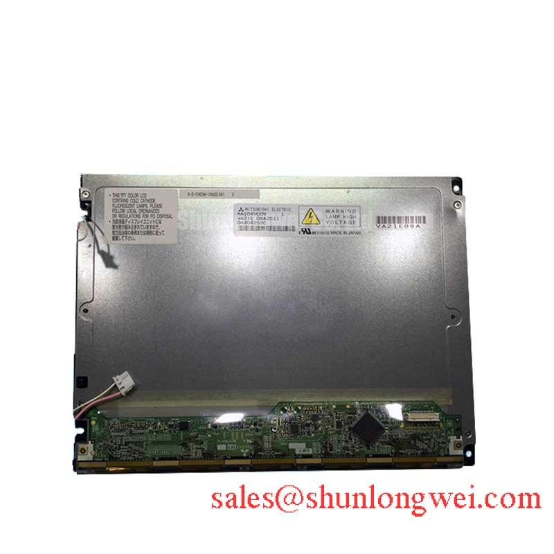
Start incoming inspection by checking the AA104VC07 label, connector condition, front-surface marks, and frame integrity before applying power. Mitsubishi Electric identifies this product as an industrial-grade LCD/HMI panel in a TFT-LCD display module format. The available factory specification context confirms the manufacturer, product category, enclosure type, and official specification status, but it does not provide verified values for panel resolution, active area, luminance, contrast ratio, viewing angle, supply voltage, interface pinout, backlight type, or operating temperature. Those values should be taken from the original equipment documentation or the panel-specific datasheet before installation.
Backlight Architecture and Insulation Testing
Do not assume that the AA104VC07 uses a particular backlight technology merely because replacement panels of a similar size may use cold-cathode fluorescent or LED illumination. The supplied factory data identifies the unit as a TFT-LCD display module, but it does not confirm a 1500–1650 Vrms cold-ignition requirement, an LED constant-current input, PWM dimming capability, or a specified half-life. A repair engineer should verify the original backlight architecture, connector assignment, ignition or enable requirements, and protection provisions from the equipment service documentation.
For a panel removed from a telematics display in a heavy mining shovel or earthmoving machine, begin with a de-energized visual examination. Look for cracked insulation around the backlight connector, carbon tracking, displaced shielding, corrosion near cable exits, and mechanical distortion of the frame. If the original assembly contains a high-voltage backlight inverter, its secondary output should be tested only with probes and fixtures rated for the measured voltage. The display module itself should not be treated as an isolated high-voltage assembly unless the original design documentation confirms that construction.
A low-temperature evaluation also requires system-level measurement rather than a rating inferred from the model number. Liquid-crystal response can change as temperature falls, producing visible gray-to-gray elongation, motion smearing, or delayed image transitions. The integrator should record the panel image, backlight drive behavior, controller timing, and heater-strip operation across the equipment’s verified environmental range. Any heater control must be assessed as part of the host display design, including thermal uniformity, condensation control, and the manufacturer’s stated limits.
When replacing a display in an existing control console, compare the original backlight connector and cable routing before selecting a mating driver. A panel with a mechanically similar outline may still require a different electrical interface. The related Mitsubishi Electric display reference AA104VC01 can be reviewed as a separate display solution, but it should not be treated as a drop-in substitute without checking mechanical dimensions, optical data, electrical ratings, and connector compatibility.
Industrial sealing is also a system responsibility. Optical bonding, perimeter sealing, and dust protection may be features of a complete HMI assembly rather than confirmed attributes of this display module. Designers should verify the enclosure sealing method, cable gland arrangement, venting, and condensation strategy when evaluating the panel for exposed or vibration-prone equipment.
Incoming Benchtop Inspection: Flexible-Connection Integrity
Place the unpowered module on an ESD-safe work surface and inspect the front glass, frame, flexible cables, connector locks, and visible bonded regions without applying pressure to the display face. The supplied specification does not confirm the internal use of COG or TAB anisotropic conductive film construction, so those technologies should not be assigned to the AA104VC07 without a manufacturer drawing or service document. The practical inspection objective is to identify transport damage and connection instability before the panel is installed in a machine.
After confirming the host controller’s documented electrical requirements, use a controlled primary-color test sequence. Display full-screen red, green, blue, white, black, and neutral-gray fields, allowing enough time for the image to stabilize. Record permanently dark pixels, bright pixels, color contamination, vertical or horizontal lines, intermittent segments, and areas that change when the cable is gently observed rather than touched. A repeatable line defect should be compared with the controller output and a known-good signal path before any conclusion is drawn about the panel bonding.
A 45-degree flashlight inspection can help separate surface contamination, backlight nonuniformity, and image-layer defects. With the display unpowered, sweep the light across the front surface and note shadows, scratches, pressure marks, and areas of uneven reflection. With the panel operating, compare the same region on white and black screens. A dark area that remains in the same physical position may require optical and electrical cross-checking; it should not automatically be classified as a driver-bond failure.
Direct sunlight testing should be treated as a design validation exercise, not as a confirmed rating for this model. The supplied factory information does not specify a greater-than-500:1 contrast ratio at 50,000 lux, anti-glare etching, optical bonding, or outdoor readability. If the target console is exposed to high ambient illumination, measure the complete assembly with its cover glass, bezel, viewing window, and any anti-glare layer installed. The result will depend on the complete optical stack and viewing conditions.
Long-term static HMI screens also require host-level image management. The available product information does not provide a burn-in, image-retention, or residual-image guarantee for the AA104VC07. Where the machine displays fixed gauges or alarm bars for extended periods, the system designer should evaluate screen rotation, controlled dimming, screen-saver behavior, and power-down timing against the panel documentation. These are integration measures, not factory specifications for the display module.
💡 Bench Tip: Use ESD protection and confirm that each flexible cable is fully seated and parallel to its connector before closing the lock; never insert or remove a display cable while the host system is energized.
Display Interface Timing, Pixel Clock, and Skew Compensation
The connector count and signal format must be verified from the original panel documentation. The supplied factory data does not confirm a 20-pin or 30-pin LVDS connector, a 3.3 V or 5.0 V logic supply, JEIDA or VESA mapping, pixel-clock limits, power-on rise-time limits, or a 100-ohm differential interface. Do not select between those values by visual similarity or by comparing the connector shell with another Mitsubishi Electric panel.
During incoming electrical evaluation, first document the host board’s connector keying, pin numbering, cable orientation, supply rails, enable signals, and ground relationship. The system integrator should verify the required supply voltage from the original panel documentation. Apply power only after confirming polarity and current protection, then monitor the supply ramp and display-enable sequence with an oscilloscope. White-screen startup, delayed image appearance, split-screen content, or intermittent synchronization should be investigated across the complete path, including controller firmware, cable seating, signal mapping, and grounding.
LVDS routing is a design consideration when the replacement is integrated into a high-EMI industrial cabinet. Differential pairs should be routed as a controlled-impedance transmission path with a continuous reference structure, matched polarity, and minimized discontinuities. A nominal 100-ohm differential target and any associated tolerance must come from the interface specification used by the host controller, not from the AA104VC07 product identity alone. The final design team should verify eye opening, common-mode behavior, pair-to-pair timing, and noise margin at the panel connector under actual switching conditions.
Skew compensation should likewise be determined by the controller and receiver timing budget. A 50 ps skew limit is not confirmed by the available factory data and should not be presented as an AA104VC07 rating. If split images or color-channel displacement appear, compare the differential waveforms at the transmitter and receiver, confirm the selected JEIDA or VESA mapping, and inspect the cable for crushed sections or shield termination problems. This approach avoids assigning a single cause to a symptom that can originate in several parts of the display link.
Power sequencing is especially important when a panel is connected to a machine computer that experiences repeated brownouts. The available specification context does not confirm a 0.5 ms to 10 ms rise-time window or a defined reset sequence. Designers should follow the original documentation for logic supply, backlight enable, display data, and shutdown order, then verify the result during cold starts, warm restarts, emergency stops, and controlled power removal. The objective is to prevent white-screen startup and residual images through validated sequencing rather than an assumed timing recipe.
Viewing-Angle and Optical Performance for Multi-Angle Consoles
The viewing technology of the AA104VC07 is not confirmed in the supplied factory parameters. It should not be described as Super-IPS, MVA, or a 85/85/85/85-degree symmetric viewing panel without an original optical datasheet. When assessing the module for a multi-angle operator console, inspect the image from the actual left, right, upper, and lower positions used by operators. Check grayscale steps, warning colors, dark-screen uniformity, and text legibility rather than relying only on a nominal viewing-angle label.
TN grayscale inversion, IPS contrast behavior, and MVA dark-state transitions are panel-technology characteristics that require verified optical data. If the replacement is being considered for a heavy mining shovel or earthmoving equipment telematics display, the complete installation should be tested with the console window, protective cover, vibration restraints, and expected operator posture. A panel that appears acceptable on a flat bench may show reflections or reduced dark-level visibility after installation behind a sloped window.
Anti-glare performance must also be verified at assembly level. The supplied data does not confirm an anti-glare coating or a contrast ratio above 500:1 at 50,000 lux. Measure reflected luminance and readable contrast with the intended cover, cabin lighting, sunlight direction, and display brightness control. Excessive surface diffusion can reduce reflected glare but soften fine text, while a glossy surface can preserve apparent sharpness and create distracting reflections. The correct balance is determined by the equipment optical path.
Mechanical reliability deserves the same attention as image quality. Check that the mounting frame does not twist the module, that the cable bend path is free from sharp edges, and that vibration restraints do not load the glass or flexible connections. The product category and TFT-LCD module construction are officially identified, but mounting dimensions, fastener requirements, vibration limits, and shock ratings are not included in the supplied parameters. Those values must be confirmed before fabrication of a replacement bezel.
For broader application planning, the guide Industrial Display and HMI Solutions provides related engineering context. Engineers comparing a different screen size or resolution may review AA084VC01, while keeping the evaluation objective: compare documented optical, electrical, mechanical, and environmental specifications before making a system change.