Content last revised on September 10, 2026
Surface Inspection and Ambient Readability Considerations
Before fitting the AA084VC01, inspect the TFT LCD display module perimeter, viewing surface, mounting points, and connector latch with power removed, then compare every original-panel label and interface record against the host equipment documentation.
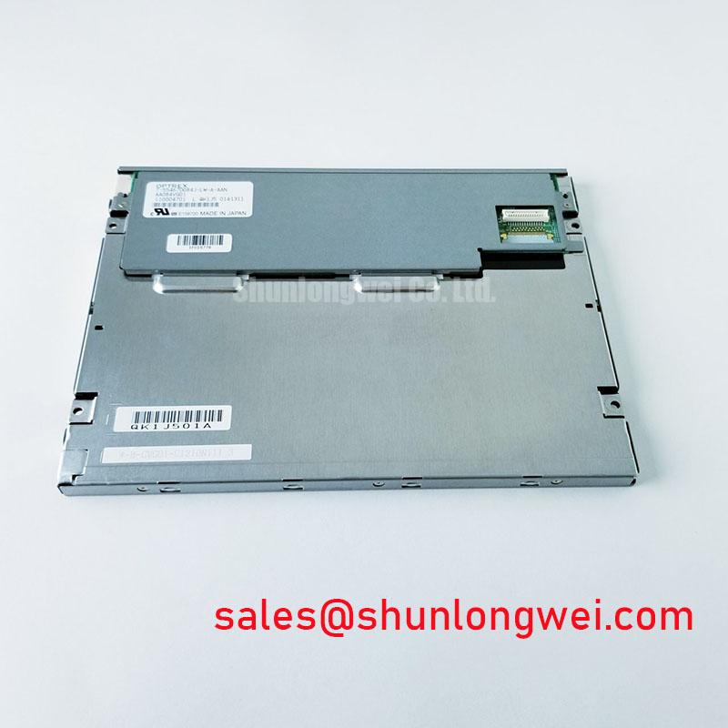
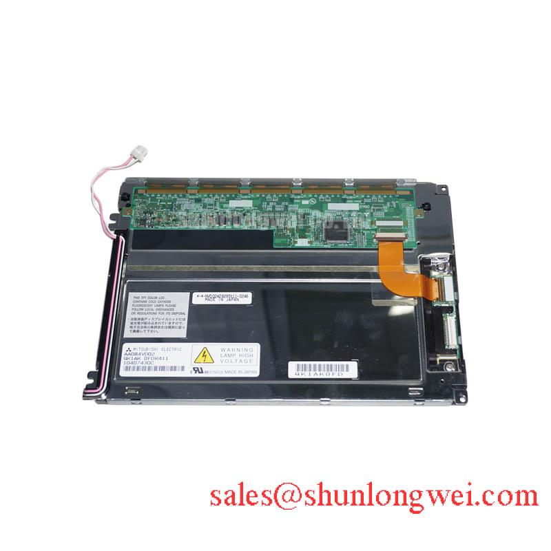
The AA084VC01 is a Mitsubishi Electric industrial grade LCD/HMI panel supplied as a TFT LCD display module. Its available official factory identification confirms the manufacturer, industrial display category, and module format. Electrical input requirements, resolution, optical values, viewing direction, backlight architecture, connector assignment, timing, and environmental ratings must be verified from the original panel documentation before replacement or system integration.
| Model | AA084VC01 |
| Manufacturer | Mitsubishi Electric |
| Product category | Industrial Grade LCD/HMI Panel |
| Module format | TFT LCD Display Module |
| Specification status | Product Identification Verified |
When an AA084VC01 module is removed from a control terminal, begin by examining the visible surface under both normal room light and a controlled oblique light source. This practical check helps distinguish a surface contamination issue, a protective film issue, a damaged cover window, and a panel level optical concern. Do not assume that the module has an anti glare treatment, anti reflective treatment, etched surface, optical bonding layer, or a specified sunlight readability value unless those characteristics are confirmed in the original Mitsubishi Electric documentation.
The available official identification confirms this product as an industrial TFT LCD display module, but it does not provide an official contrast ratio, luminance value, viewing cone, TN, IPS, or MVA classification. Claims such as stable contrast above 500:1 at 50,000 lux, or symmetric 85 degree viewing performance, must therefore not be assigned to AA084VC01 without the corresponding factory optical specification.
As a Design Consideration, panel readability in a high ambient control room depends on the whole display stack rather than the LCD module alone. The front window material, enclosure depth, gasket contact, display angle, surface cleanliness, room lighting direction, and protective overlay can each influence apparent contrast and glare. For a high voltage substation protection or SCADA dispatch console, maintenance staff should compare the removed panel with a known good console under the same lighting conditions before deciding whether the concern lies in the LCD, front window, or enclosure assembly.
Grayscale behavior should also be evaluated carefully. A visible tonal shift when the operator changes position may originate from the panel technology, host video configuration, surface reflections, or mechanical stress introduced by the mounting frame. It should not be treated as proof of a particular LCD mode without official confirmation. If the display is installed behind a protective cover, inspect for uneven pressure at the perimeter. Local pressure can create apparent brightness variation or mura that changes when fasteners are loosened and retightened in an even sequence.
Optical bonding and additional front sealing are system level modifications rather than verified AA084VC01 factory features. When an enclosure is exposed to dust, humidity, or frequent temperature cycling, designers should assess whether the existing front gasket and cover arrangement still provide uniform contact without transferring stress into the module. The broader integration principles are discussed in The Ultimate Guide to Industrial TFT LCD Technology.
⚠️ Maintenance Note: Inspect the enclosure gasket and cooling air path during scheduled service, because trapped dust and uneven front frame pressure can reduce display clarity and create localized visual stress.
Signal Integrity and Differential Noise Verification in High-Vibration Bays
Before connecting an AA084VC01 replacement module, record the original cable routing, connector orientation, latch position, strain relief arrangement, and chassis bonding path. The verified factory information available for this model does not identify the display interface as TTL, LVDS, FFC, or any other specific signaling method. The system integrator should verify the required supply voltage, interface type, connector pinout, signal timing, and power sequencing from the original panel documentation and the host controller design.
Pixel jitter, intermittent horizontal bands, sparkles, or an unstable image can arise from several conditions. Possible contributors include a partially seated connector, cable flex damage, contamination at the contact area, grounding discontinuity, controller output instability, or electrical noise coupling from adjacent equipment. In facilities containing variable frequency motor drives, observe the display while the relevant equipment starts and stops, then compare the video path with a known good signal path using appropriate test equipment. A symptom should not be attributed to differential signaling noise unless the actual interface and measured waveform support that finding.
As a Design Consideration, cable shielding and chassis grounding should be evaluated as a complete installation practice. If the host equipment documentation specifies a shield termination method, retain that arrangement during service. Changes to cable length, routing, ferrite parts, or grounding locations should be validated at the installed system level, particularly where vibration and nearby power equipment can affect cable retention and signal integrity.
Repeated cable motion deserves attention in HMI maintenance. Flexible display cables can be damaged when bent sharply at the connector exit, pinched by a rear cover, or left unsupported in a vibrating cabinet. Use the original routing geometry where possible and ensure that the connector latch is fully engaged without placing a sustained pull load on the contact area. If the panel is mounted to a hinged service door, inspect the cable through the full door travel rather than only in the closed position.
Low ambient temperature can change LCD response behavior and can also expose pre existing connector or power issues. The official factory data provided for AA084VC01 does not state an operating temperature range, response time, heater provision, or heater control method. Do not specify operation at subzero temperatures or add a heater strategy based on generic panel assumptions. Where condensation is possible, the enclosure designer should verify thermal control, sealing, and power up conditions against the equipment requirements.
For equipment families requiring a separate display solution review, TCG084SVLPAANN-AN20 can be examined as a related display product reference. It is not an automatic electrical or mechanical substitute for AA084VC01. Compatibility must be established from documented interfaces, mechanical drawings, optical requirements, and host controller timing.
Vertical Line Defect Investigation and Panel Fault Localization
A single narrow vertical line should be investigated with a controlled image test before the display module is condemned. With the equipment safely isolated and the original interface requirements confirmed, present solid red, green, blue, white, and black images from a stable source. Record whether the line remains at the same screen location through each image, whether it changes with cable movement, and whether it appears before or after the host system has completed its normal startup sequence. This preserves useful evidence without assuming a single internal failure mechanism.
Use a low angle flashlight inspection only as a visual aid. A dark region that becomes more visible under oblique illumination can indicate that the visible issue involves the illumination path, front cover, polarizing surface, or contamination. A line that remains sharply fixed across different test images may indicate a panel level issue, but it can also require verification of source data and connector continuity. The available official data does not identify the internal driver structure, so AA084VC01 faults should not be described as a specific chip on glass fracture or column driver open circuit without manufacturer level evidence.
Mechanical handling is especially important after a display has been removed from a tight industrial bezel. Avoid twisting the module while releasing the mounting hardware. Release fasteners progressively and support the assembly so that the display is not suspended by its cable. When reassembling, align the module before final tightening and distribute frame load evenly. This is a Design Consideration for industrial TFT LCD handling, not an AA084VC01 factory torque specification.
Power sequencing should be checked when the panel shows a temporary white screen, residual image, delayed picture appearance, or intermittent startup. These observations can result from host controller behavior, supply ramp characteristics, enable control, cable seating, or the display itself. The system integrator should verify the required power order, data enable timing, and shutdown behavior from the original panel documentation. No AA084VC01 clock jitter limit, data hold time, or timing margin is stated in the official factory information provided here.
Long duration static HMI pages also deserve a measured maintenance response. If faint image retention is observed, document the displayed content, duration, ambient conditions, brightness control state, and recovery behavior after normal operating changes. Avoid claiming permanent panel damage from a single observation. A controlled comparison with another known good display in the same equipment can help determine whether the visible condition follows the module, the video source, or the application screen.
For a hardware replacement evaluation, AA104VC01 is a related Mitsubishi Electric display model that may be reviewed against the system requirements. It should only be considered after mechanical dimensions, connector details, power requirements, interface signaling, timing, and front bezel fit have been checked against documented equipment requirements.
Backlight and Illumination Supply Troubleshooting
Do not connect an external inverter, LED driver, or backlight supply to AA084VC01 based on an assumed backlight type. The official factory information supplied for this model identifies it as a TFT LCD display module but does not confirm CCFL illumination, dual channel operation, inverter topology, LED illumination, striking voltage, dimming method, PWM capability, or backlight lifetime. Values such as 1500 to 1650 Vrms, 1000:1 dimming, and 50,000 hour performance are not verified AA084VC01 specifications and should not be used for service decisions.
If a panel has no visible image, first establish whether the host controller is generating valid video and whether the display’s documented supply and enable conditions are present. A faint image observed only under external light may suggest that the image path and illumination path need to be investigated separately, but it does not independently confirm a failed lamp, inverter, LED driver, or panel. Follow the equipment manufacturer’s safety procedures when measuring any energized display or power circuit.
Acoustic noise from a display area can originate from several parts of the assembly, including a power conversion stage, enclosure vibration, cable movement, or adjacent equipment. Isolate the sound source through controlled observation rather than making a component level assumption. Any replacement driver or inverter must match the documented electrical requirements of the original system. The module, its display interface, and its illumination supply should be treated as a coordinated assembly.
For high voltage substation protection and SCADA dispatch console maintenance, confirm that the panel mounting frame is clean, the rear ventilation route is unobstructed, and the sealing surfaces are dry before returning equipment to service. Check that no cable is trapped between the rear cover and chassis, that the display connector latch remains secure, and that the host system completes its documented startup and shutdown sequence. These steps support reliable integration without asserting unverified electrical characteristics for the AA084VC01.