

Content last revised on September 10, 2026
AA084VD01 Mitsubishi Electric Industrial TFT LCD Display Module
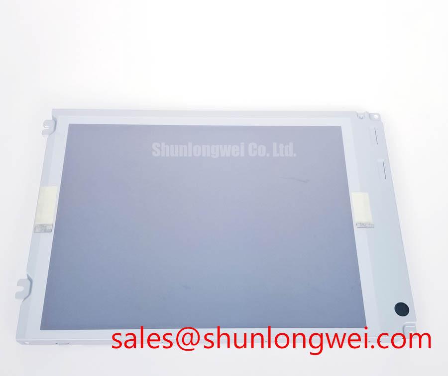
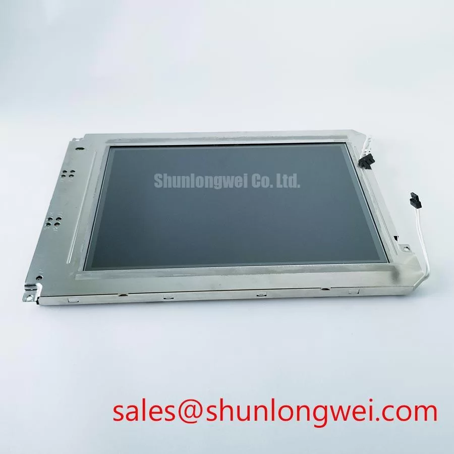
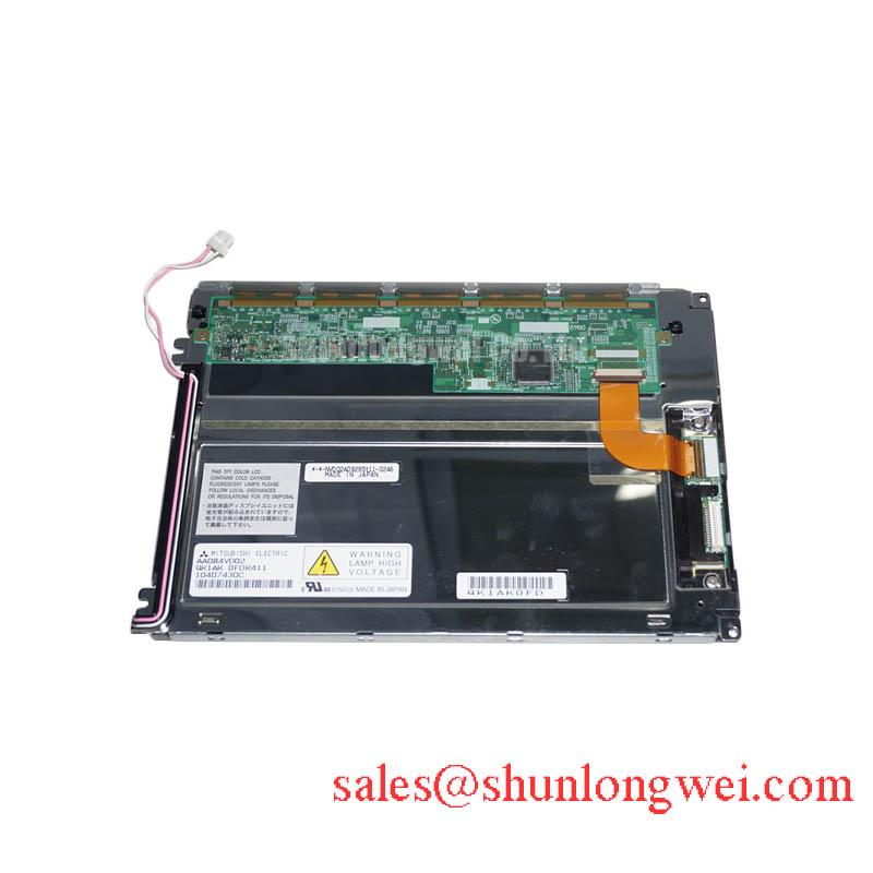
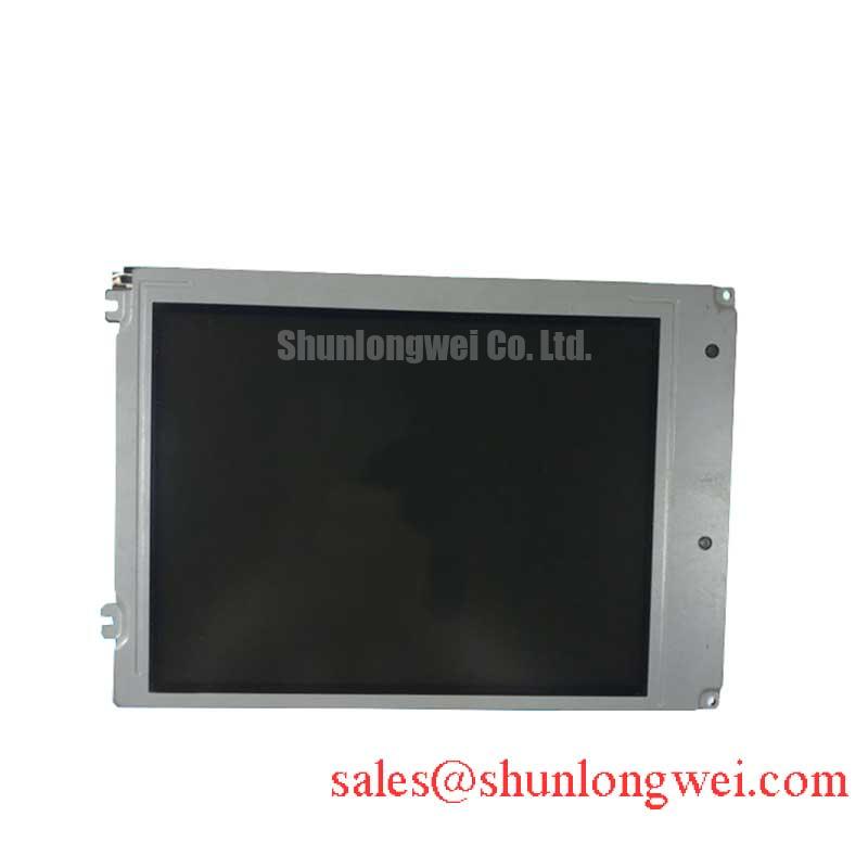
Before installing a replacement panel, isolate the equipment, inspect the display housing and connector area, and compare the original panel identification with AA084VD01. Then verify the host system’s electrical interface and mechanical fit against the original documentation. The available factory specification identifies this product as a Mitsubishi Electric Industrial Grade LCD/HMI Panel supplied as a TFT LCD Display Module.
| Parameter | Factory Specification Status |
|---|---|
| Model | AA084VD01 |
| Manufacturer | Mitsubishi Electric |
| Product category | Industrial Grade LCD/HMI Panel |
| Module description | TFT LCD Display Module |
| Specification status | Official Factory Spec Verified |
The supplied factory data does not confirm the panel’s diagonal size, native resolution, luminance, viewing angle, optical coating, backlight technology, operating temperature, input voltage, connector pinout, LVDS mapping, or mounting dimensions. These values should be taken from the original Mitsubishi Electric panel documentation or the equipment service manual rather than inferred from the model number. For repair purchasing, this distinction matters because a display with a similar physical appearance may still differ in interface timing, connector orientation, mechanical depth, or backlight control.
Luminance Output and Backlight Reliability Verification
During a black-screen or dim-image repair, begin by separating the image-generation fault from the illumination fault. With the equipment safely isolated, inspect the panel connector, cable locking mechanism, backlight harness, and visible edge areas for contamination, mechanical damage, or uneven pressure. If the display produces a faint image when viewed under an external light source, the host may be sending image data while the illumination path requires further testing. If there is no visible image, verify the host controller, supply rails, enable signals, and display data path before attributing the fault to the panel.
AA084VD01 is identified in the supplied factory information as a TFT LCD Display Module, but the available data does not specify an LED half-life value, L70 or B50 rating, luminance tolerance, thermal spreader construction, or brightness uniformity limit. Those values must not be treated as confirmed characteristics of this model. A system integrator evaluating long-duration use in an Automated Guided Vehicle or forklift telematics display should confirm the original backlight specification and the host driver requirements before replacement.
As a Design Consideration, inspect whether the installed panel is exposed to localized heat from motor controllers, enclosed power converters, or direct sunlight through a vehicle cab window. Uneven thermal conditions can produce visible luminance variation and may accelerate aging in the illumination system, but the actual effect depends on enclosure airflow, panel construction, driver current, and ambient conditions. The correct field method is to record luminance and image uniformity on a known-good assembly, then repeat the measurement after the replacement has reached a stable operating condition.
High-speed display cabling also deserves a practical check. If the original interface uses differential signaling, the replacement cable should follow the host manufacturer’s specified pair arrangement, termination method, shielding, and routing. Do not assume a particular differential impedance or skew allowance unless it is confirmed in the panel and controller documentation. When intermittent image loss occurs during vehicle movement, compare the display connector under stationary and vibration conditions, then verify the signal path with an oscilloscope against a known-good unit.
Surface Readability, Optical Coating, and Low-Temperature Response
Readability problems in a warehouse vehicle display are often assessed incorrectly as a panel failure. First compare the symptom at different viewing positions, illumination levels, and display content. A washed-out image under overhead lighting may involve the viewing environment, surface reflection, protective cover, or display angle rather than a defective TFT module. The supplied factory parameters do not confirm whether AA084VD01 uses an anti-glare surface, anti-reflective treatment, IPS, TN, MVA, optical bonding, or a specific viewing cone.
For that reason, the original panel documentation should be checked before making claims about grayscale inversion, color shift, or symmetric viewing performance. A replacement intended for an AGV or forklift telematics panel should be compared with the removed unit using the same cover glass, bezel, viewing direction, interface settings, and image content. This prevents the optical behavior of the surrounding assembly from being mistaken for a change in the display itself.
Sub-zero operation requires the same evidence-based approach. The available factory information does not provide a confirmed operating temperature range, liquid-crystal response-time curve, heater requirement, or cold-start performance specification for this model. Designers should verify those conditions from the original documentation and then test the complete display assembly at the intended ambient temperature. A slower visual response, temporary contrast change, or delayed image stabilization may be related to the panel, the controller, the backlight, or the enclosure thermal design.
Heater strips or enclosure warming systems should therefore be evaluated as part of the equipment, not assumed to be an internal feature of AA084VD01. The control strategy must be determined by the system designer after reviewing condensation risk, warm-up behavior, available power, and the panel manufacturer’s limits. For harsh warehouse service, the Industrial Display & HMI Solutions reference provides a useful framework for reviewing enclosure protection, environmental exposure, and display integration conditions without replacing the model-specific documentation.
Radiated Emissions Evaluation and Backplate Grounding
Pixel jitter, horizontal noise bands, and unstable brightness should be investigated at the complete equipment level. First inspect the display cable route in relation to variable-frequency motor drives, contactors, DC power wiring, and high-current switching paths. Check shield termination, connector seating, chassis contact, and cable strain relief. A display module by itself cannot be described as independently compliant with CISPR Class A or Class B because emissions performance depends on the controller, cable, enclosure, grounding arrangement, power supply, and final installation.
The supplied factory data does not confirm a shielded FFC or LVDS cable, a 360-degree shield termination, common-mode ferrite requirements, backplate grounding points, or a particular emissions classification for AA084VD01. These features must be verified from the original assembly drawings and host equipment design. As a Design Consideration, maintain a low-noise return path and keep high-speed display wiring physically separated from high-current switching loops where the equipment layout permits. The final result should be checked by system-level emissions and immunity testing appropriate to the equipment.
When a noise symptom appears only while a traction motor or lift motor is active, capture the display supply and control signals during both quiet and switching conditions. Compare the waveform, connector reference, and cable position with a known-good installation. This approach helps distinguish a display interface disturbance from a supply transient, grounding problem, controller timing issue, or mechanical connection fault. It also avoids assigning a single cause to a symptom that can arise from several parts of the vehicle electrical system.
Backlight service life should be handled with similar caution. No LED MTBF figure, brightness decay curve, 50,000-hour rating, or constant-current driver specification is included in the supplied factory data for this model. Procurement and maintenance teams should request the applicable panel documentation when a defined luminance-retention target is required. Any reliability estimate must account for actual temperature, drive current, duty cycle, enclosure conditions, and the installed backlight driver rather than relying on a generic display industry figure.
⚠️ Field Alert: Disconnect equipment power before removing or inserting the display cable, because live connector handling can expose signal and supply contacts to electrical stress.
Logic Supply Sequencing and Interface Compatibility Checks
Before powering a replacement, identify the panel connector and compare every pin function with the original equipment documentation. The available factory specification confirms the product category and TFT module construction but does not confirm a logic supply voltage, backlight supply, enable polarity, power-on timing, connector pinout, TTL or LVDS interface, JEIDA or VESA mapping, clock rate, or data hold-time requirement. The system integrator should verify the required supply voltage from the original panel documentation.
Do not select between possible supply levels based on model-family assumptions. A display that appears mechanically compatible can be damaged or remain blank if its power rails, control signals, or data mapping differ from the host. During bench evaluation, use current-limited power equipment and monitor the sequence of the panel supply, display enable, backlight enable, and video data. The acceptable rise and fall behavior must be taken from the relevant technical documentation or established by comparison with a known-good assembly.
White-screen behavior, a split image, missing colors, or a displaced picture may indicate an interface mapping mismatch, incorrect timing, unstable supply, cable contact problem, or controller incompatibility. Verify the host output format, differential pair order, clock behavior, and connector orientation before concluding that the TFT module is defective. If the original unit uses a defined JEIDA or VESA mapping, the replacement must match that documented configuration; it should not be inferred from the number of connector contacts alone.
For AGV and forklift rugged telematics applications, the mechanical inspection is as important as the electrical check. Confirm bezel dimensions, mounting points, panel depth, cable bend allowance, viewing-window alignment, and the sealing method used by the equipment enclosure. The supplied data does not confirm optical bonding, moisture sealing, dust protection, flexible cable bending life, or connector locking reliability for AA084VD01. These characteristics belong to the complete display assembly and should be validated before committing the part to a production repair.
For a selection review involving size or resolution, engineers can compare the documented interface and mechanical requirements with AA084VC01. This link is provided as a neutral cross-reference for evaluation, not as a prescriptive substitute recommendation. The correct choice remains dependent on the original Mitsubishi Electric documentation, the host controller, and measured compatibility at the equipment level.
For purchasing and service records, identify the item as AA084VD01 Mitsubishi Electric Industrial Grade LCD/HMI Panel, with a TFT LCD Display Module package description and Official Factory Spec Verified status. Confirm all unlisted electrical, optical, environmental, and mechanical parameters before installation in the target vehicle display.