



Content last revised on September 10, 2026
Mitigating Gray to Gray Response Time Escalation during Cold Start Machine Power Up
At cold machine start, begin with a visual observation before changing controller settings. Power the host system through its normal sequence, then check whether the panel produces a stable raster, whether text transitions appear delayed, and whether the behavior changes only after the enclosure reaches a more moderate temperature. Slow grayscale movement can arise from the liquid crystal response itself, but it can also be associated with timing configuration, unstable panel supply rails, a marginal signal cable, or a controller that has not completed its intended initialization sequence.
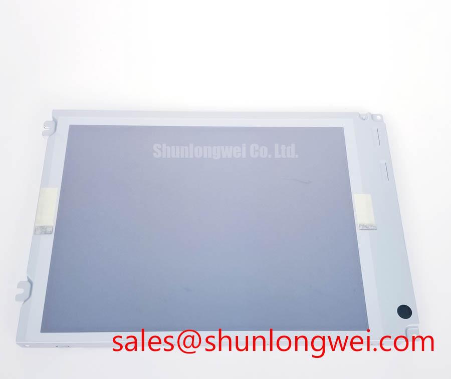
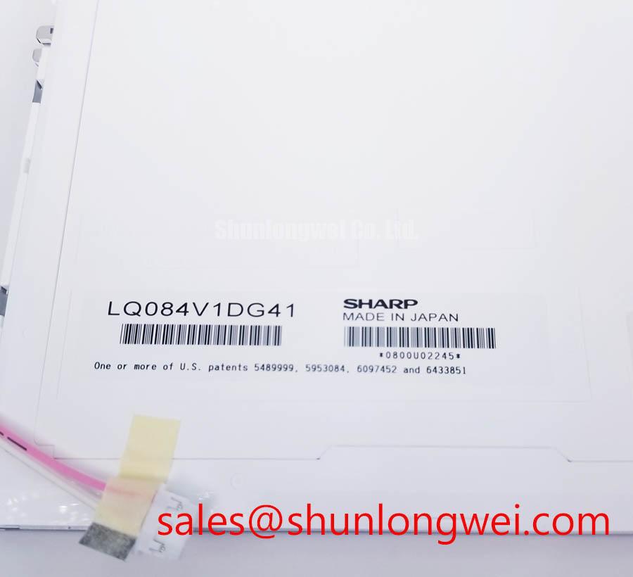
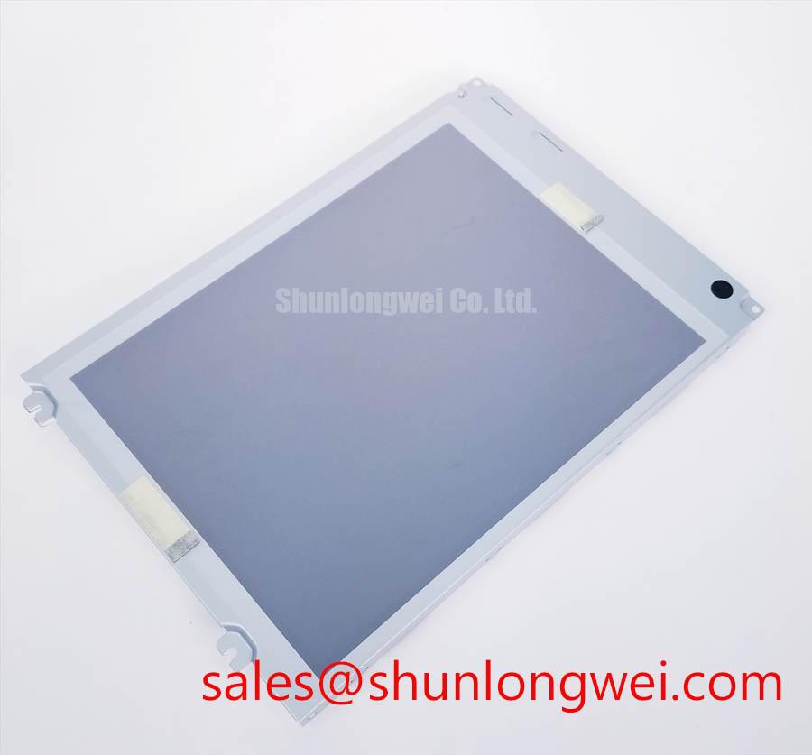
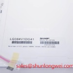
The available factory identification record for LQ084V1DG41 does not state a qualified operating temperature range, Gray to Gray response time, contrast ratio, sunlight readability, anti glare treatment, or perimeter seal construction. Claims concerning operation from minus 30°C to plus 85°C, contrast above 500:1 at 50,000 lux, or coating type should therefore not be assigned to this specific Sharp module without the applicable factory documentation.
Design Consideration: When a panel is installed in a location exposed to repeated low temperature starts, assess the complete display assembly rather than treating image lag as a panel only issue. Review the enclosure thermal path, cable strain relief, controller startup behavior, power rail stability, and the time relationship between panel logic power and incoming video data. A controlled comparison with a known good display path can help distinguish a temperature related optical effect from a system timing issue.
For an operator terminal considered for a hazardous petrochemical Zone 2 location, the panel itself should not be presented as proof of explosion protection, ingress protection, or installation approval. Those properties are determined by the complete certified enclosure, cable glands, power architecture, installation method, and applicable site requirements. The display can be evaluated as a replacement part within that assembly only after its physical and electrical characteristics are matched to the approved equipment configuration.
When investigating cold start complaints, keep the original controller board and display cable in the diagnostic loop where possible. Replacing several parts at once can obscure whether the visual symptom is related to the panel, a cable connection, or the host electronics. If a different display option is being assessed for legacy equipment, LM64P10 can be reviewed as a separate display product, but its suitability must be determined through documented mechanical, electrical, optical, and interface comparison rather than size class alone.
Suppressing Pixel Jitter & Horizontal White Lines Induced by Adjacent 400V Motor Drives
When horizontal white bands, intermittent pixel movement, or image instability appears near a variable frequency motor drive, inspect the signal path before assuming the TFT module has failed. Observe whether the artifact changes with motor acceleration, braking, output frequency, cabinet door position, cable routing, or display brightness setting. Such changes may indicate coupling into the display interconnect, while a persistent fixed line can require separate investigation of the panel, controller output, or connector contact condition.
The official information provided for LQ084V1DG41 does not confirm an LVDS interface, TTL interface, FFC format, shield termination arrangement, common mode filtering, or supported dimming method. The system integrator should verify the required interface from the original panel documentation. JEIDA and VESA data mapping must also be confirmed at the controller and panel level, because an incorrect mapping arrangement can produce abnormal color order, contrast behavior, or image data errors without indicating a defective display.
🔧 Bench Diagnostic: Disconnect power before reseating the panel cable, then inspect connector lock engagement and cable routing before applying any controller configuration change.
Engineering Recommendation: Keep display signal wiring physically separated from high energy motor conductors where enclosure geometry allows, use the shielding approach defined by the equipment design, and evaluate grounding continuity at the cable and chassis interfaces. A shield connected without regard to the host grounding scheme can shift rather than remove common mode noise, so validation should be performed with the complete cabinet energized under representative operating conditions.
For differential display links, the commonly used 100Ω differential impedance target is a general interface design consideration, not an official electrical parameter of this model. Pair geometry, return path continuity, connector transitions, and pair to pair timing alignment should be assessed against the actual transmitter and receiver requirements. If pixel clock jitter is suspected, examine the waveform at the known good controller path and compare it with the installed path using appropriate high impedance measurement techniques.
Specifications such as a PWM dimming frequency of 200Hz to 1kHz and duty cycle linearity are not confirmed for the LQ084V1DG41 by the provided factory record. The integrator should identify whether the original display assembly uses a separate backlight driver, how enable and dimming signals are referenced, and whether the replacement assembly preserves the original power sequencing. Where a related display solution is under review, LMS700KF01-001 should be evaluated from its own documentation rather than treated as an assumed backlight driver for this Sharp panel.
High Nits Edge Lit LED Rail Thermal Dissipation & PMMA Light Guide Plate Preservation
Start a brightness related inspection by checking the display enclosure for blocked airflow, uneven pressure from the bezel, localized heating around adjacent power electronics, and signs that the original thermal interface arrangement has been altered. Uneven brightness, visible edge shading, or brightness drift after warm up can have several possible contributors, including the display module, the backlight supply, the mechanical stack up, or external thermal loading from the host equipment.
The available official factory information does not specify luminance, backlight technology, LED rail construction, light guide material, thermal resistance, backlight current, L70 value, B50 value, or lifetime for LQ084V1DG41. It would therefore be inaccurate to describe this model as a high nits edge lit LED product or to assign preservation characteristics to an internal PMMA light guide plate without the corresponding Sharp specification.
Design Consideration: In any display assembly that includes an illuminated backlight system, localized temperature should be managed through the equipment enclosure and the mounting arrangement. The mechanical design should avoid concentrating force at display edges, should preserve the original panel support points, and should prevent nearby heat sources from raising the panel temperature beyond the limits established in the applicable documentation. System engineers should validate brightness uniformity and surface temperature after assembly under the intended operating load.
Do not use brightness control as an isolated diagnostic result. If visual flicker occurs during dimming, compare the panel supply, the controller enable signal, the dimming command, and the backlight power source while the equipment is operating. The observed issue may relate to interaction among these elements rather than to a single component. Where the host design uses pulse width modulation, its operating frequency and control polarity must be taken from the original circuit documentation; no PWM range is verified for this specific module in the information available here.
Replacement planning should include the physical fit around the panel perimeter. A bezel opening that presses directly onto the active display area can create optical nonuniformity, while insufficient retention can permit vibration movement at the connector. These are assembly conditions, not published attributes of the LQ084V1DG41. Preserve the original mounting concept and verify that gasket compression, enclosure clearances, cable bend path, and service access remain appropriate after the panel is installed.
Surface Anti Glare & Anti Reflective Etched Coating for High Ambient Readability
Under high ambient light, first inspect the external viewing stack rather than attributing poor readability to the LCD panel alone. Check the condition of the protective window, any applied film, the bezel recess, enclosure angle, contamination on the viewing surface, and reflected light sources behind the operator. A display that is readable on the bench can become difficult to view after it is placed behind a scratched cover lens or positioned opposite a bright process area.
The supplied official information for LQ084V1DG41 does not confirm an anti glare coating, anti reflective coating, etched surface treatment, viewing angle, TN mode, IPS mode, MVA mode, or an 85°/85°/85°/85° viewing specification. These features must be verified from the original Sharp documentation or from a controlled comparison against the panel presently installed in the equipment. A coating used on an external cover lens should also be identified separately from any finish that may be present on the LCD module itself.
Engineering Recommendation: Evaluate readability with the complete front assembly fitted, including the final cover window and sealing components. The useful observation is whether alarms, text, color states, and trend graphics remain distinguishable from the intended operator position under the site lighting condition. If glare is the dominant issue, changes to enclosure orientation or the protective window may be more relevant than changes to the display module.
For high noise cabinets, signal integrity should be reviewed together with visual performance. The often cited differential skew budget of 50ps is a system level design reference, not an official limit for this model. Designers should maintain matched differential routing according to the actual panel interface requirements, avoid discontinuous return paths, and verify image stability during realistic electrical noise events. If the panel uses a non differential interface, those LVDS principles should not be applied as a substitute for its documented signal requirements.
Touch capability is not identified in the available factory data. Engineers should not assume that the LQ084V1DG41 includes a capacitive or resistive touch layer, supports gloved operation, or provides reliable wet touch behavior. If the original operator station includes touch input, confirm whether that function belongs to a separate overlay, controller board, or front glass assembly. For broader inspection methods covering display interface selection, optical checks, and panel integration boundaries, refer to The Ultimate Guide to Industrial TFT LCD Technology.