


Content last revised on September 10, 2026
Single Vertical Hairline Defect & Sub-Pixel Column Driver Open-Circuit Localization
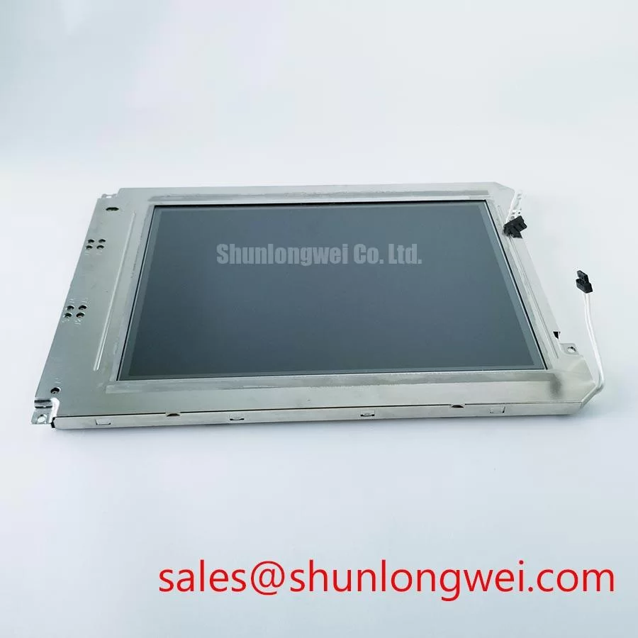
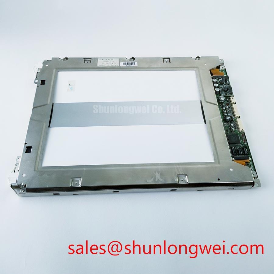
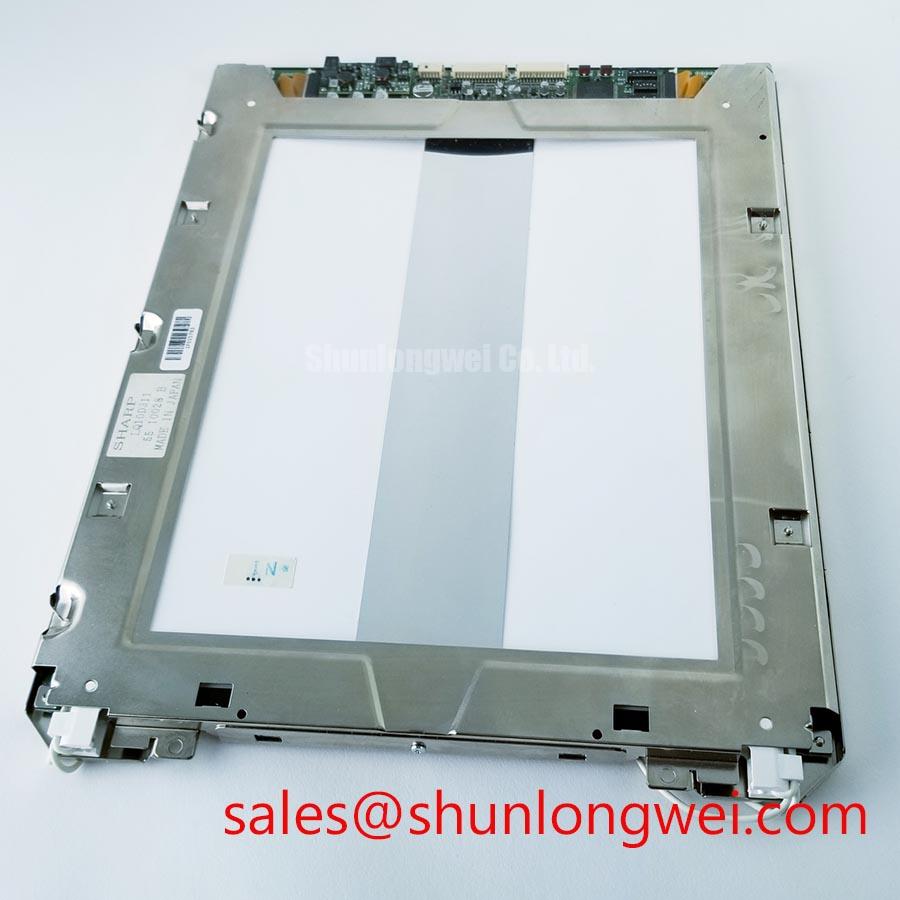
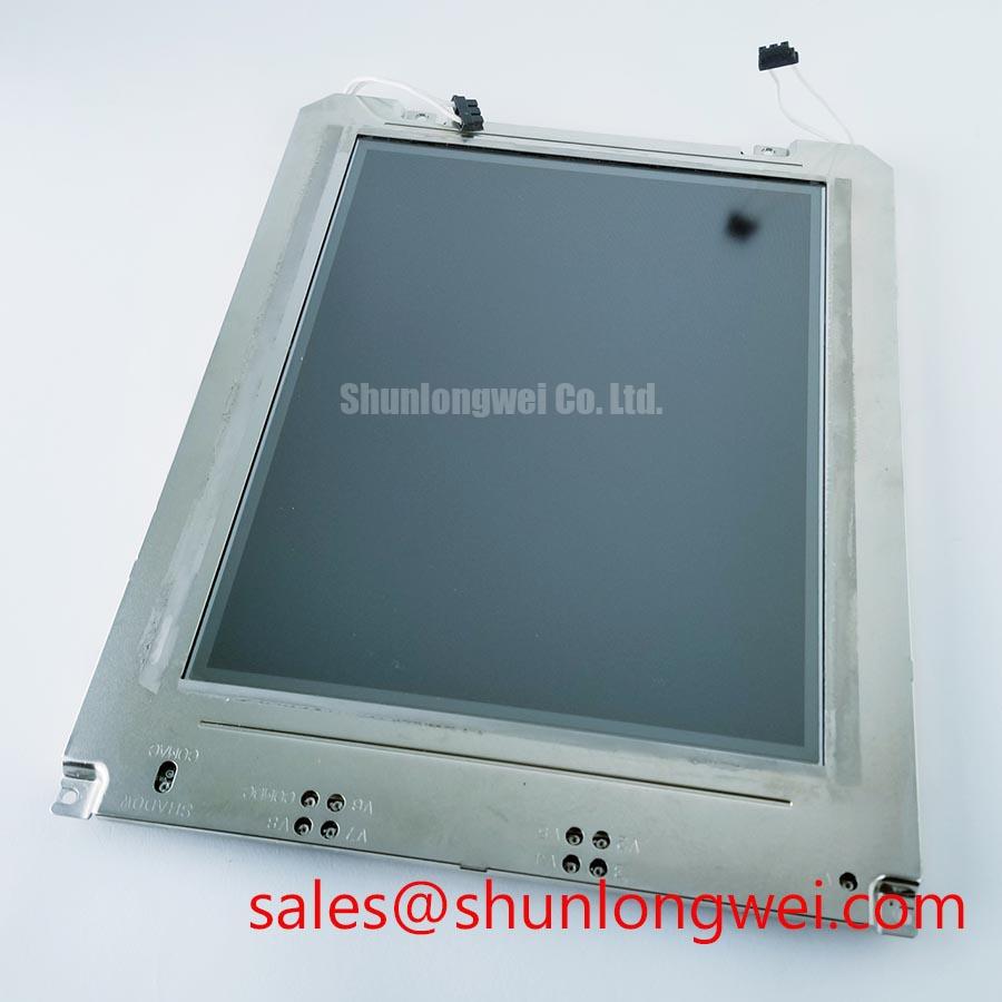
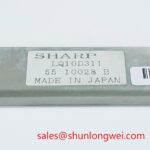
With power isolated, inspect the Sharp LQ10D311 display perimeter, front surface, connector area, and flexible interconnect routing before reconnecting the panel to the host controller. The available factory identification confirms an industrial-grade TFT-LCD display module; the system integrator should verify the required supply voltage, signal format, timing, connector pinout, mounting geometry, and backlight arrangement from the original equipment documentation before energizing the replacement.
A stable vertical hairline that remains visible on black, red, green, blue, and white test screens can help separate an image-path issue from a backlight illumination issue. Begin with a full-screen primary-color test sequence, allowing each image to remain on screen long enough to observe whether the defect is continuous, intermittent, color-dependent, or influenced by gentle chassis movement. A single fixed line can be associated with the panel signal path, a connector contact condition, a controller output, or damage within the display assembly. It should not be assigned to one cause without comparison against a known-good signal source or panel.
Use an angled flashlight only as a visual aid. At approximately 45 degrees to the inactive screen, the technician may see a faint image beneath a dark surface if the image data path is active while the illumination path is absent. This observation does not prove a backlight fault by itself, but it narrows the inspection toward panel power sequencing, illumination control, cabling, and the host-side interface. If the line is still visible under this inspection condition, record whether it tracks a source image, stays in one physical column, or changes when the cable is reseated with power removed.
🔧 Bench Diagnostic: Disconnect and reconnect the display cable only after the controller and panel supplies are fully de-energized, because live connection can create misleading symptoms or stress the interface.
Design Consideration: where the original system uses a differential display interface, controlled impedance and pair-to-pair timing remain host-system requirements rather than published specifications of the LQ10D311. A nominal differential impedance of 100 Ω with permitted system tolerance and a tightly controlled skew budget are common interface practices, but the equipment designer must validate waveform integrity at the actual cable length, connector arrangement, grounding scheme, and controller output setting. In high-noise cabinets, a line defect that appears only during motor operation may warrant oscilloscope comparison with the known-good signal path before the panel is condemned.
Do not repeatedly bend a flexible cable near its termination while searching for an intermittent image fault. Observe the cable’s installed bend route, strain relief, connector latch engagement, and any point where enclosure hardware can compress the cable. A symptom that changes with vibration may arise from the host connector, cable, panel connector, mechanical strain, or support hardware. Inspection should progress from accessible external interfaces toward the display module rather than relying on visual assumptions about internal construction.
When a replacement study is required, the LM190E08-TLG6 can be reviewed as a separate display option. It must not be treated as an automatic replacement for the LQ10D311. The purchasing and repair team should compare active area, outline dimensions, mounting points, connector location, interface standard, electrical requirements, and original controller compatibility before considering any alternate panel.
Industrial EMI Noise Immunity, Chassis Shielding Continuity & Common-Mode Ferrite Chokes
Examine chassis bonding continuity from the equipment enclosure to the cable shield termination before attributing horizontal bands, pixel shimmer, or intermittent image movement to the LQ10D311. In industrial control cabinets, display cables can pass near switching power supplies, contactors, servo amplifiers, and variable-frequency motor drives. The panel can reveal interference that originates elsewhere in the installation, particularly when the visible disturbance changes with motor speed, load state, or switching activity.
Design Consideration: a shielded display cable is most effective when its shield is terminated according to the original equipment grounding architecture. A 360-degree shield termination can offer a lower-impedance path for high-frequency noise than a long drain-wire connection, but enclosure safety practices, cable construction, and the host design determine the correct implementation. The repair technician should restore the original shield contact surfaces, remove oxidation or contamination where appropriate, and check that cable clamps do not pinch conductors or place uneven force on the connector body.
Common-mode ferrite components can be evaluated when conducted or radiated interference is suspected, but their selection is a system-level Engineering Recommendation rather than an official LQ10D311 requirement. Their effectiveness depends on cable impedance, noise spectrum, shield termination, grounding topology, and signal margin. Installations should be checked with the actual controller operating under representative load conditions. A ferrite that improves one operating state but creates signal degradation in another should not be regarded as a completed corrective action.
Where the original design uses differential signaling, preserve matched routing through replacement cable work and avoid unnecessary stubs, sharp folds, or unsupported cable sections. Differential-pair impedance consistency and timing alignment are important because excessive mismatch can reduce noise margin and produce behavior that resembles a failing panel. The correct acceptance test is a stable image across intended screen patterns, normal equipment operating modes, and the relevant cable movement expected during enclosure service.
Mechanical installation also affects apparent noise problems. A display frame tightened unevenly can introduce local pressure, visible luminance variation, or intermittent contact stress that is mistaken for electromagnetic interference. Use the original mounting scheme, ensure that gasket surfaces are clean, and distribute fastening load evenly. The official supplied specification identifies the product as an industrial-grade TFT-LCD module but does not provide a mounting torque value. Fastener torque, washer selection, and compression limits must therefore follow the equipment manufacturer’s mechanical documentation.
For display-system comparison during a repair review, LM64P10 is available as a related display solution reference. Its inclusion does not establish electrical, optical, mechanical, or interface compatibility with the LQ10D311. Each panel and controller combination requires independent verification against the original machine documentation.
Constant Luminance Output Control & Illumination-Life Reliability Verification
Check uniformity with a controlled full-white image after the panel has reached the equipment’s normal thermal condition. Dark edge zones, local bright areas, or gradual color variation can originate from the display module, illumination hardware, enclosure pressure, contaminated optical surfaces, or an unstable supply path. Photographing the same test image at a fixed exposure setting can provide a useful maintenance record, provided that camera settings and ambient light remain consistent between inspections.
The supplied factory information confirms the LQ10D311 as a TFT-LCD display module, but it does not state an illumination technology, luminance rating, illumination current, L70 value, B50 value, or lifetime rating. These values must not be inferred from the model designation. If the original panel documentation contains illumination-life data, service teams can use those published conditions as a reference when comparing brightness trends. Without such documentation, objective inspection of uniformity, startup behavior, flicker, color shift, and thermal condition is more reliable than assigning an unsupported operating-life figure.
Design Consideration: localized heat near a narrow display edge can accelerate changes in adjacent display materials and can make brightness non-uniformity more visible. The enclosure designer should provide an unobstructed thermal path where the original equipment design requires one, while avoiding concentrated clamp force on the display frame. Any aluminum support rail, heat spreader, gasket, or thermal interface used around the module must be assessed for flatness, electrical clearance, compression behavior, and its effect on front-surface appearance.
Static industrial HMI pages deserve routine review. Fixed alarms, process diagrams, and navigation elements can leave temporary residual image effects on some display technologies when held for long periods. This is a usage consideration, not an official LQ10D311 retention specification. When the host controller permits it, maintenance teams can assess the practical benefit of screen blanking, page rotation, reduced dwell time for noncritical static pages, and proper power-down sequencing. Any such control should be validated against the equipment’s operating and safety requirements.
⚠️ Maintenance Note: During scheduled cabinet service, inspect cooling air paths, display gaskets, mounting points, and cable strain relief for dust buildup, compression damage, or moisture pathways.
Condensation control is equally important. A cold panel brought into a warmer humid enclosure can collect moisture on surfaces and connectors, producing intermittent optical or electrical symptoms. Allow environmental conditions to stabilize before applying power where the equipment procedure permits. For installations evaluated near salt-laden air, outdoor exposure, or navigation-console environments, enclosure sealing and corrosion control remain properties of the complete equipment assembly, not a published qualification claim for the LQ10D311 module.
Preventing Frame Lag & Image Smearing in Cryogenic Storage & Outdoor Industrial Facilities
Before judging response behavior, compare the LQ10D311 under a stable power source, known-good video source, and controlled ambient condition. A slow transition, trailing image, pale startup screen, or temporary residual pattern can be influenced by liquid-crystal temperature behavior, controller timing, panel supply sequencing, the source signal, or moisture exposure. The supplied factory information does not provide an operating-temperature range, gray-to-gray response specification, contrast ratio, sunlight readability value, or anti-glare coating specification for this model. Those characteristics must be verified from the original panel documentation rather than estimated from general TFT-LCD practice.
At low temperature, many liquid-crystal displays can exhibit slower visual transitions because the liquid-crystal material responds differently as viscosity rises. This is a general Design Consideration and does not establish a temperature rating for the LQ10D311. If a panel is being evaluated after cold storage, allow it to reach a suitable stable environment before applying diagnostic conclusions. Inspect the front polarizer, frame edges, connector region, and perimeter seal area for physical change, then test the panel with moving grayscale and high-contrast patterns under the equipment’s intended operating conditions.
Power sequencing requires the same discipline. A white screen, momentary image instability, or residual image at shutdown may be linked to the host controller’s rail order, data enable timing, illumination control, or a supply that decays unpredictably. The system integrator should verify the sequence required by the original LQ10D311 documentation and host board. Do not create substitute timing values from a similar panel, because compatible-looking connectors and comparable display categories do not establish identical electrical behavior.
Frame lag complaints should also prompt a mechanical check. Uneven bezel pressure, a distorted support plate, cable tension, or a gasket that has hardened with age can alter how a panel sits within the enclosure and can create visible artifacts during temperature change. Release and reapply mounting pressure according to the equipment procedure, confirming that the panel is supported evenly and that no part of the enclosure bears against the active viewing area.
For outdoor equipment and bridge-console assessments, sunlight legibility should be evaluated at the installed viewing angle and actual ambient light level, not inferred from a generic contrast threshold. Glare is influenced by front-surface condition, protective window spacing, enclosure reflections, and operator position. Engineers needing broader context for interface checks, display selection factors, and structured fault isolation can refer to The Ultimate Guide to Industrial TFT LCD Technology. The final decision should remain based on the original machine requirements and verified LQ10D311 documentation.